Welcome to my MLA Blog This blog documents my weekly learning journey as part of the Master of Landscape Architecture (Year 1) at the University of Greenwich. It serves as a reflective space where I collect notes, thoughts, and visual material from the courses Landscape Design Technology and Design Experimentation & Communication. Each entry combines key aspects of the lectures with my own reflections, sketches, and examples from practice. The aim is not only to record what was taught, but also to explore how these ideas can be applied in design processes and future landscape projects.
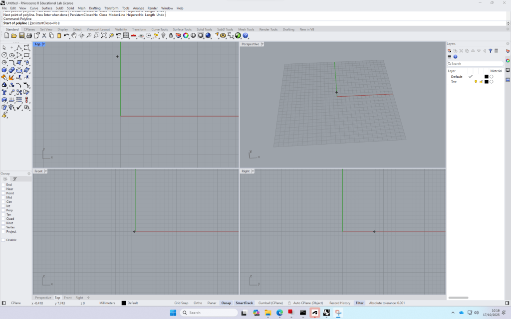
Rhino is a modelling software that works great with autoCAD. It’s easy to import your cad-plans and then visualize it. It’s also a good toll to build models from scratch.
Build up: Four views -> can be opened by double clicking on the
The commands are very similar to AutoCAD.
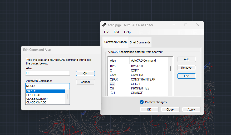
+ with the time, the program remembers your favourite commands, so tying in few letters
Layers
Bottom bar, very similar to autocad
Create a rectangle (Top view)
Switch to Perspective view and type in “ExtrudeCrv”, then drag the midpoint of the line and type in the distance (height) of the block.
Copy the block and type in the required distance, repeat.
Switch to Front view to create the Rails. draw the outline of the right side of the rail, join the polylines, fillet the edges. Then mirror the profile to complete this
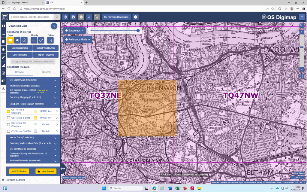
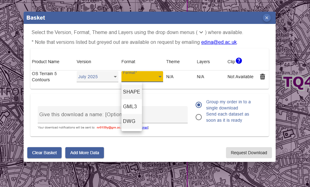
How to create a Terrain model from digimap terrain downloads:
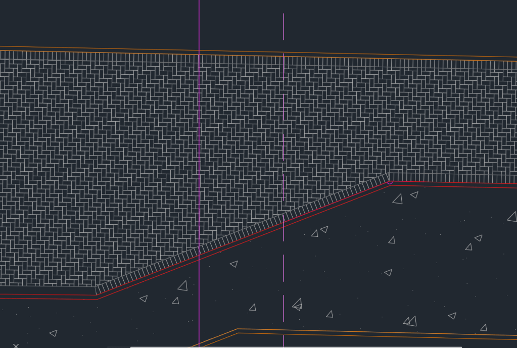
Today’s last AutoCAD introduction class was about practicing Hatching and adding Detailed information to our Project-Site Plans.
To get started I added the detailed Information of the pavers. However for our final Site Plan Layouts of the scale 1:200, it doesn’t make sense to add so much Detail to the Plan as it will only be visible as a black surface.
Part of the Stone Paving on my Site Plan
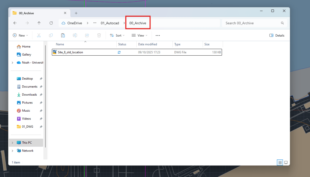
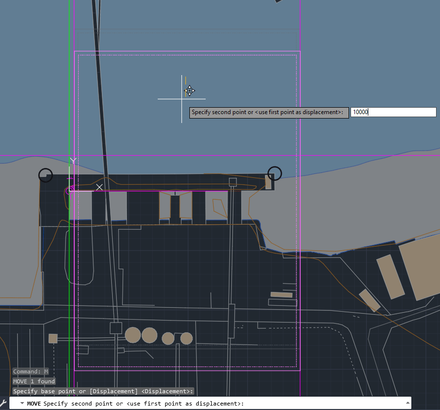
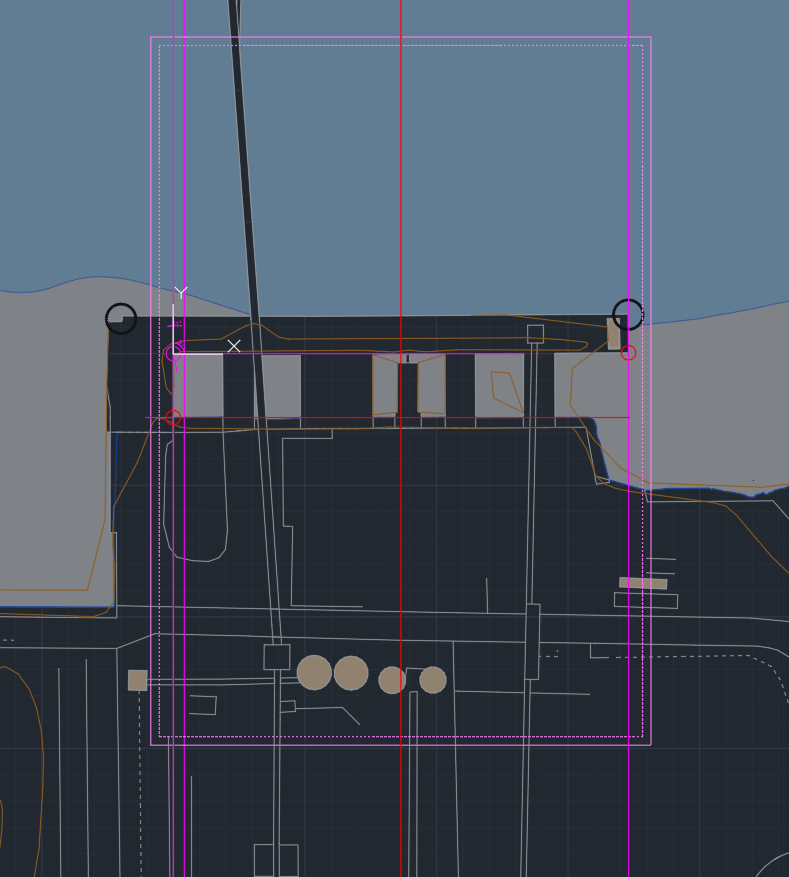
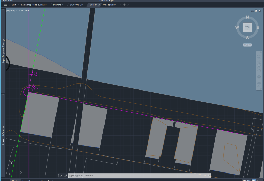
I also spent some time had to move my Site to include the Thames Path and reduce the amount of water area, which is important for the further process of our Design Project.
Archive of old Site Plan
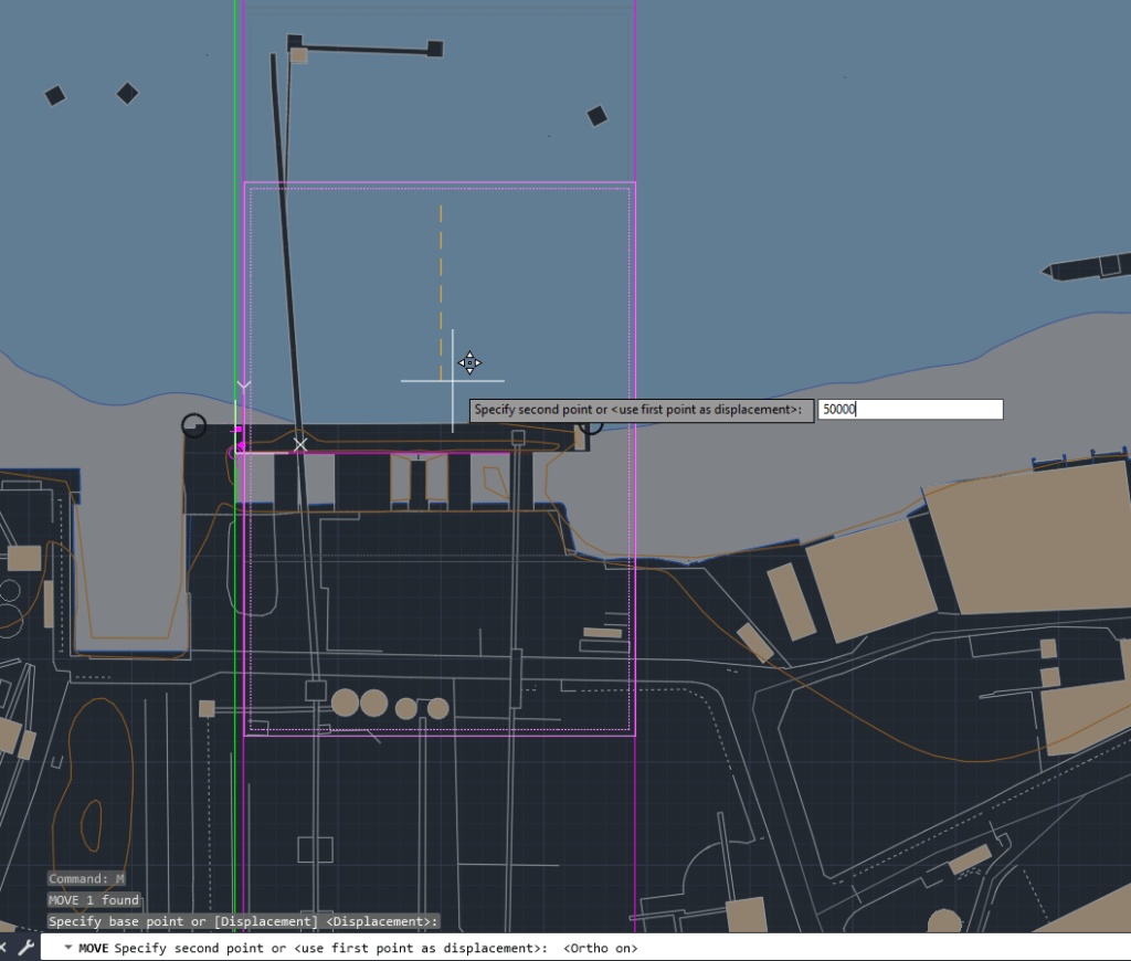
Moving the site down (ortho)
Final site location now includes the Tames Path and Part of the industrial
Minerals and active soluble salts -> S0-S2 Ratings
Bricks below damp proof course level
Cavity wall insulation -> min 50mm air space between brick and insulation
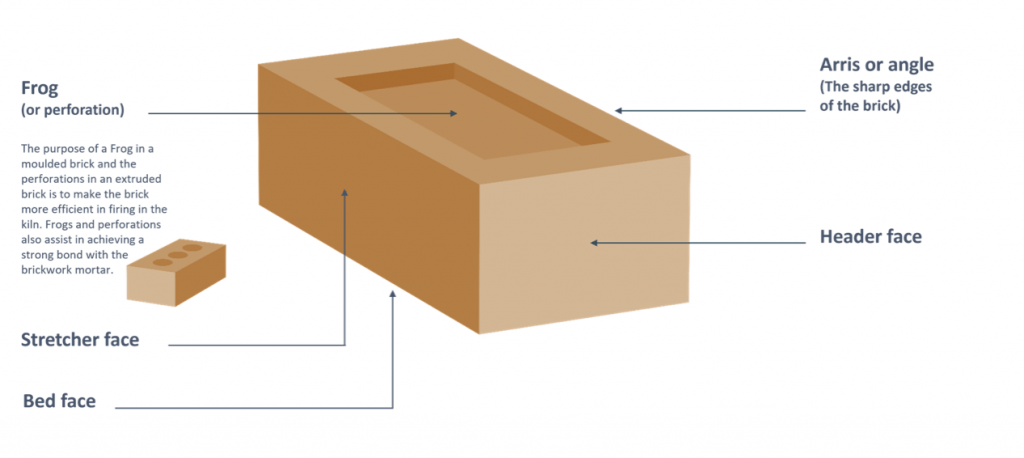
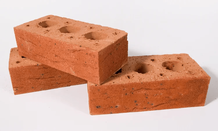
Configuration and brick size -> UK standard size: 215×102.5x65mm -> different to CH (150/175/200)
Co-ordinating size (ex. standard): 225×112.5x75mm -> Including mortar joint
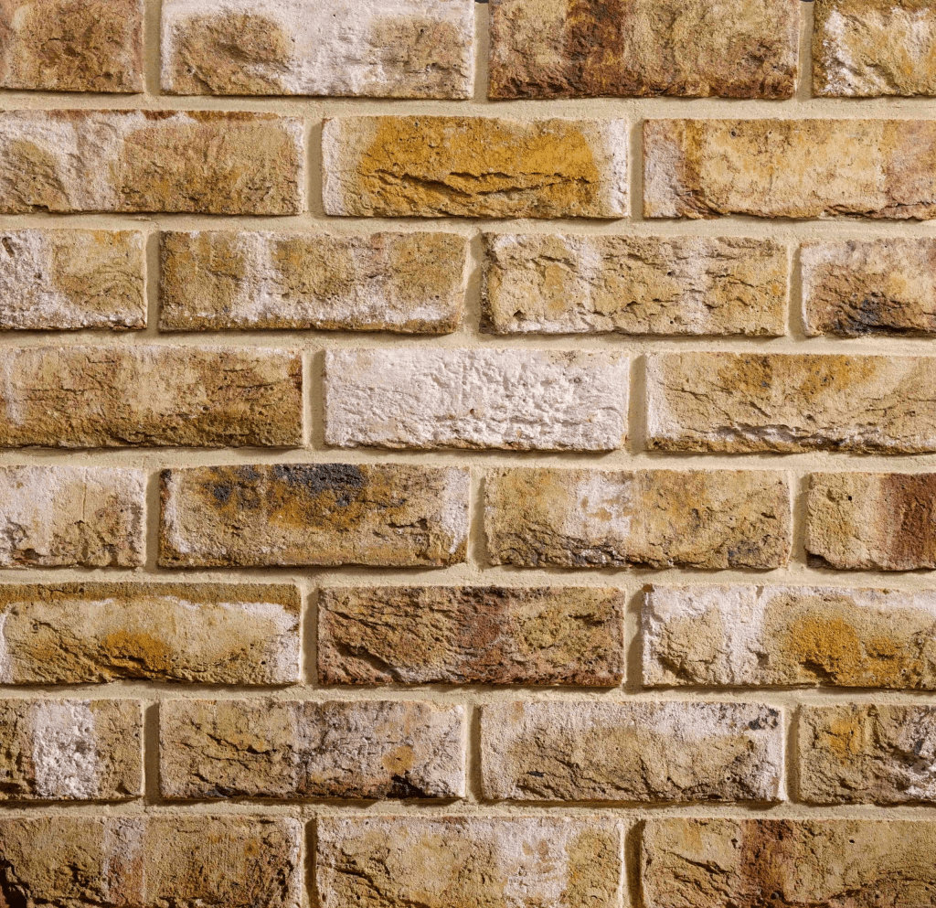
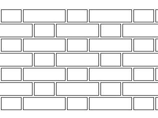
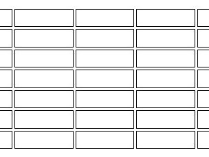
Mortar joint profiles: Bucket handle (only one I used in practice), Weather struck, Flush, Recessed
Difference mortar color can make on a brick wall
A Limit of brick laying of 1200mm a day is recommended!
This avoids possible mortar displacement.
Building movement:
Movement joints -> no more than 3m to the first from corner, after that every 6m. (free standing wall), Building wall the distance from the corner should not extend 6m.
What struck me most about today’s session was the direct comparison of approaches to using brick as a building material between the UK and Switzerland.
Many of the requirements or recommendations differ from the Swiss standards I learned during my training as a draftsman in structural engineering.
Example: a detail of a cavity wall construction from my Swiss course material.
I found it remarkable how the tolerance space behind the outer brick wall differs so greatly—just 10–20 mm in Switzerland compared to the recommended 50 mm in the UK. The standard dimensions of Swiss bricks also deviate considerably from the UK norm, most likely because the “common” Swiss dimensions refer to bricks that are usually plastered or integrated into a ventilated wall system.
Another striking point is how brick, especially as exposed masonry, appears to be much more widespread and historically rooted in the UK than in Switzerland. Apart from old factories or in some cases farmhouses, historical examples of exposed brickwork are rarely found in my home region.
The regulations concerning the spacing of the vertical elements of fall protection barriers also differ. In Switzerland, the maximum permitted distance is 12 cm, whereas in the UK it is only 10 cm!
Due to the Digimap files having the scale in meters, we are always going to scale the drawings by 1000 to achieve the scale in mm that we will use in our drawings.
I realized that the standard unit-settings are often set to INCHES. So I use -dwgunits to set the units to MILIMETERS to prevent any issues with the layout/drawing later on.
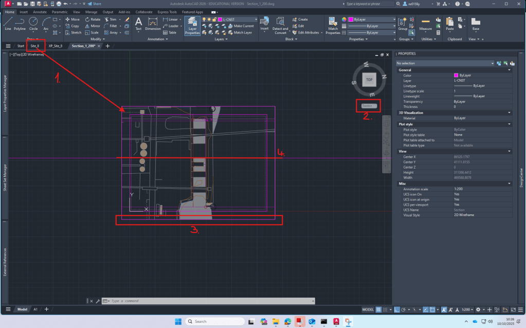
Section
For the section I XREF the downloaded and scaled file from digimap.
By using the file as an XREF I can:
make sure that the original file is not damaged in any way
work directly with my own layers without having to deal with the huge amount of layers from the digimap file
clip the xref on a certain cutout if I only need one part of the plan to be visible
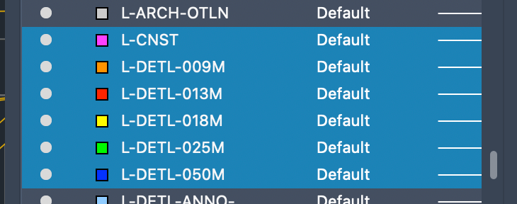
Layers
To be able to work with different lineweights I use the Layer setting I used to work with in practice.
The lineweight is always written in the layer-name and is also differenced by the colors of the layers.
We spent most of the day learning about the important steps of drawing a Section.
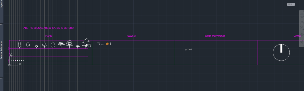
Besides the Section I decided to spend some time to start my own block-library. I already have a lot of files from practice, filled with different blocks of trees, people, vehicles, furniture and many more.
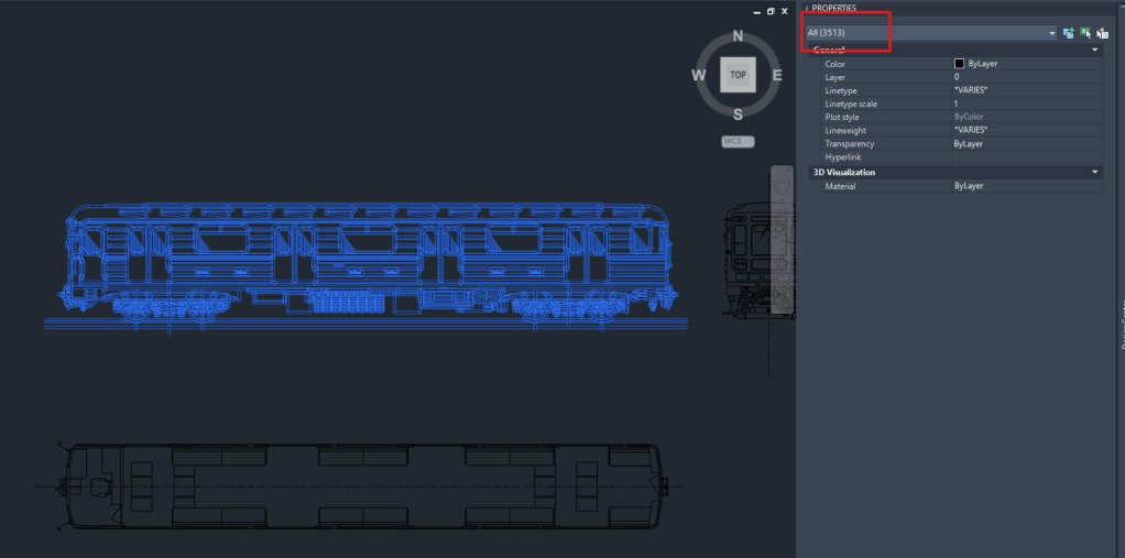
A big Problem with blocks, especially if they are downloaded from the Internet is the file size. Depending on the way they are created, blocks can exist out of hundereds, if not thousands of lines/vertexes, arcs or even ❗️splines❗️.
Example of a block, I downloaded from the web today, containing over 3000 Objects!
So I think it’s very important to clean up the blocks and minimize the amount of data that it contains. !Cleaning up a block can be a very time consuming action!
Due to some rather exhausting experiences with large file sizes (especially sections) and crashing computers, I became very picky when it comes to choosing blocks for my drawings. That’s why I only added few trees and other blocks to my library yet that are simple and cleaned up in a lot of hours of moving or deleting lines
As usually you could add lots of additional detail and information to the section.
From my experience I can say: more detail creates more visual attraction, BUT as soon as the Information is too detailed for to be visible in the final, scaled layout, it’s too much!
Roots: Are not a mirrored protection of the tree. -> Rootball is wide and quite flat. 90% of the roots are in the top meter of soil.
Photosynthesis: Water and carbondioxide is transported through UP the stem to the leaves.
Product: Sugar and Oxygen going DOWN (floams)
A lot of sugar is not adding to groth, it’s going down into the root system for storage.
In spring the plans need energy and they take it from the storage.
Plant Naming:
Example: Pyrus calleryana ‘Redspire’
Pyrus: Genus
calleryana: species
‘Redspire’: cultivar
Nursery production:
Goal: Similar plants. Know what your getting if ur talking about a plant.
Production goals: Uniform, Consistent Clones of Plants. -> needs to be done
Genetic mutation leads to differences over time in species!
How to ensure you clone plants in the right way:
Chipbudding (the two plants are very closely related)
remove a single bud and implant it in the donoughtplant.
Tie the two together and they fuse.
Then the rootstock is cut back to th bud that it grows from there.
Cutting: -> go over it again
Adventious root formation
Roots
Arise from tissue other than existing roots
What to look for in a nursery:
conistent groth pattern (can be short but needs to be uniform)
Seed production: can be used if diversity is needed (natural) and the similarity isn’t important
Nursary production systems:
Soil shaken off method:
trees are scooped out the ground with and the soil is shaken off
trees are kept in bags: black inside (no light inside), white outside (reflect)
Rootballed plants (close to enea method)
scooped out with the soil to keep the it in contact with roots
Bundeled up in “jutesack” material and in metal grid
the greater the rootmass, the better
rootballs are kept hydrated
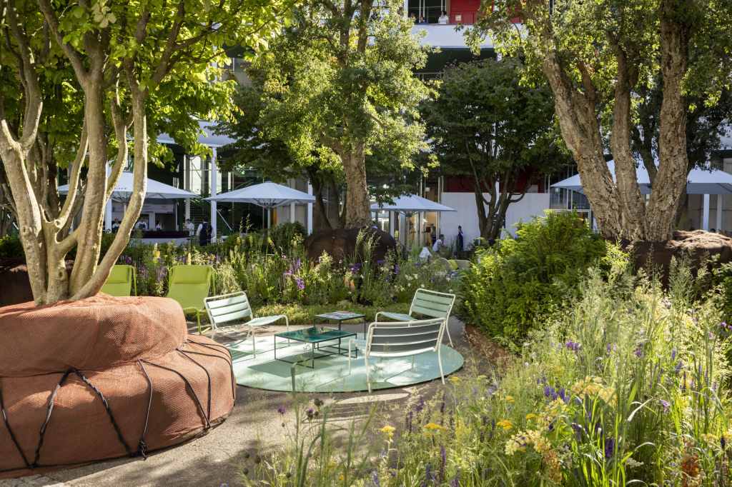
Project for the “Art Basel” by my former employee, enea landscape architecture. Trees were kept inside the jute material instead of using planters to give a raw insight of method the company uses to moves trees and provide unique seating areas at the same time.
Specifications of transplanting: -> read again
Use “setzlinge” that are as small as possible because it minimizes the “shock” of transplanting
Bigger ones require more carefulness -> see enea
Allow the tree to move after planting to get stronger. -> put support structure fairly low
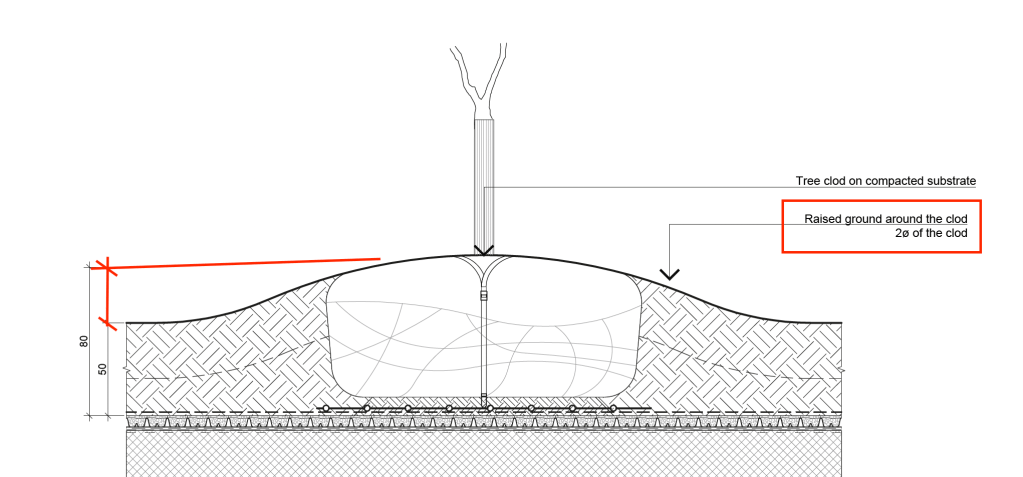
Never plant plants too deep!
If the tree is planted too low, the roots will be suffering and in worst case the tree will not survive. Example shows how this important step was implemented in plans when I worked in practice.
Transportation
Tree is taken by the rootball
Loading basically in responsibility of the nursary
Unloading: responsibility of the LA contractor
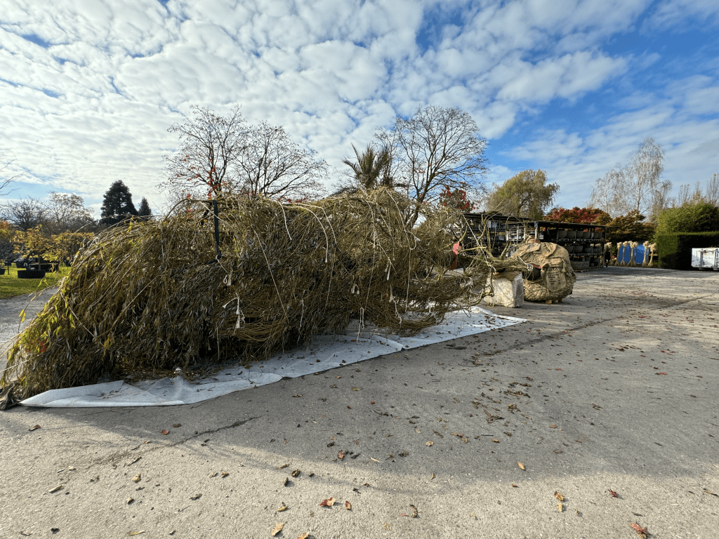
Transportation of a large Salix x pendula
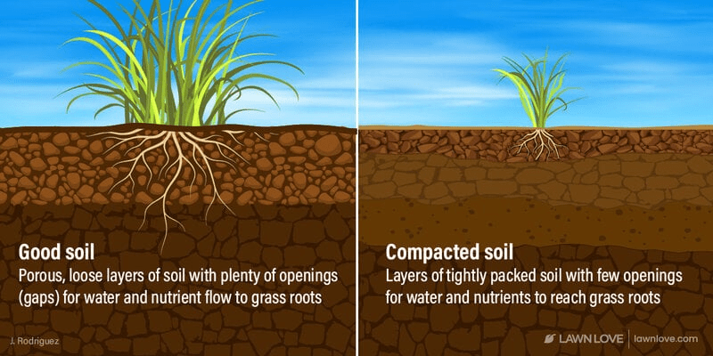
Soil
living habitat/ecosystem
Provides support
Moisture
Drainage
Provides access to fungi
Ratio between sand, silt and clay
Compacted soil
no water gets through
smells bc no air
Good soil:
50% Solid
25% Water
25% Air
High clay soil expands and leads to cracks.
Soil improvment:
Clay: add sand -> to make a difference, so much sand needs to be added, it’s not economically bearable.
Higher clay content: easy to get too dense to have an impact on planting
Use of compacted Soil
as a support of Structures on top of it
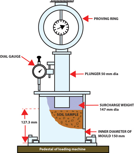
CBR
Measures the ability of a ground to support a load, relative to a bucket of rocks from California. measured by loading the ground to see how much it affects it.
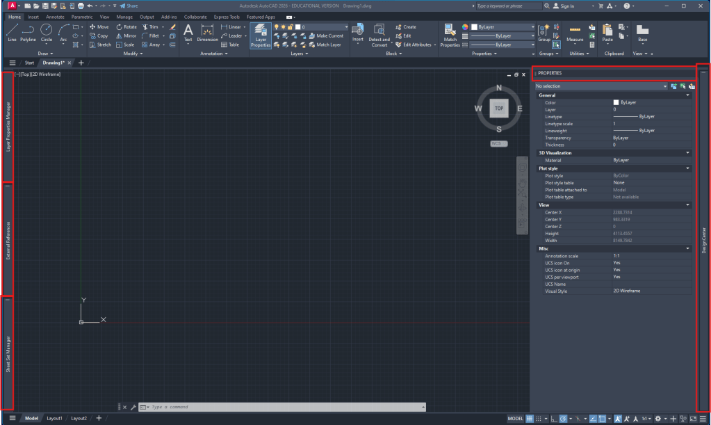
This first lesson, lead by Kris, was all about a steady introduction to the basics of Autocad.
Due to my previous work with Autocad as a draughtsman in a Landscape Architecture office, I already have a good understanding of the whole planning process in Autocad
Autocad workspace setup:
Layer manager (attached to the left)
External references (attached to the left)
optionally SheetSet manager (attached to the left)
Properties (right side)
AdCenter (attached to right side)
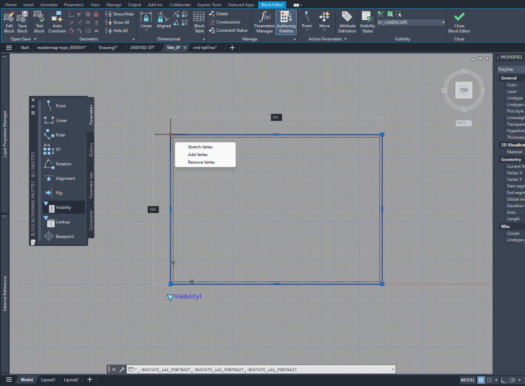
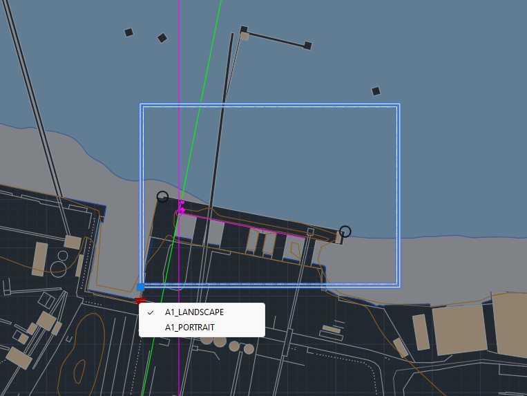
To create the layout it’s helpful to see the outline in the Model Space. To do that I created a block of the size of the A1 layout and added Block creation
Week 2
Digimap
Due to the Digimap files having the scale in meters, we are always going to scale the drawings by 1000 to achieve the scale in mm that we will use in our drawings.
I realized that the standard unit-settings are often set to INCHES. So I use -dwgunits to set the units to MILIMETERS to prevent any issues with the layout/drawing later on.
Section
For the section I XREF the downloaded and scaled file from digimap.
By using the file as an XREF I can:
make sure that the original file is not damaged in any way
work directly with my own layers without having to deal with the huge amount of layers from the digimap file
clip the xref on a certain cutout if I only need one part of the plan to be visible
Layers
To be able to work with different lineweights I use the Layer setting I used to work with in practice.
The lineweight is always written in the layer-name and is also differenced by the colors of the layers.