Welcome to my MLA Blog This blog documents my weekly learning journey as part of the Master of Landscape Architecture (Year 1) at the University of Greenwich. It serves as a reflective space where I collect notes, thoughts, and visual material from the courses Landscape Design Technology and Design Experimentation & Communication. Each entry combines key aspects of the lectures with my own reflections, sketches, and examples from practice. The aim is not only to record what was taught, but also to explore how these ideas can be applied in design processes and future landscape projects.
This first lesson, lead by Kris, was all about a steady introduction to the basics of Autocad.
Due to my previous work with Autocad as a draughtsman in a Landscape Architecture office, I already have a basic understanding of the whole planning process in Autocad
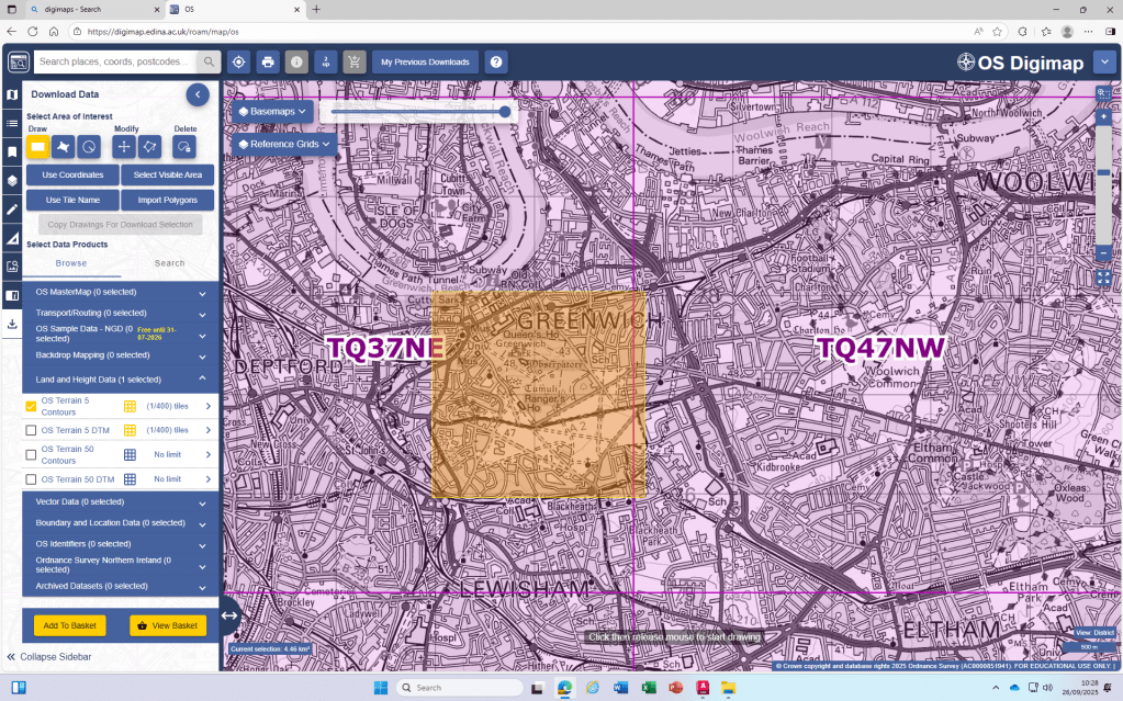
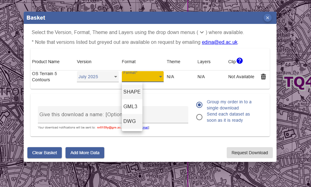
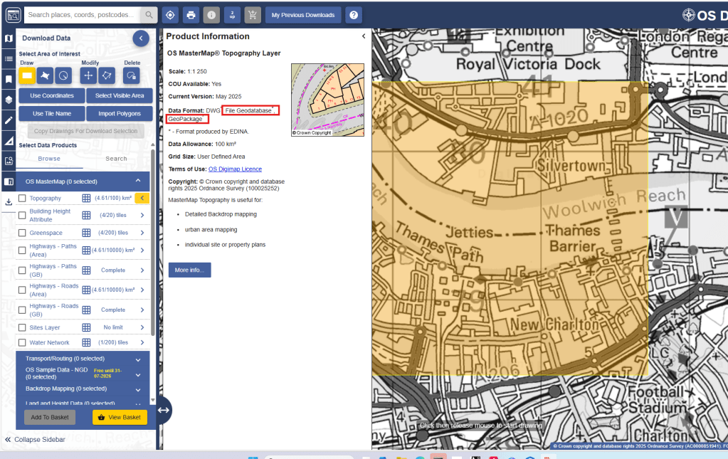
DWG download from Digimaps:
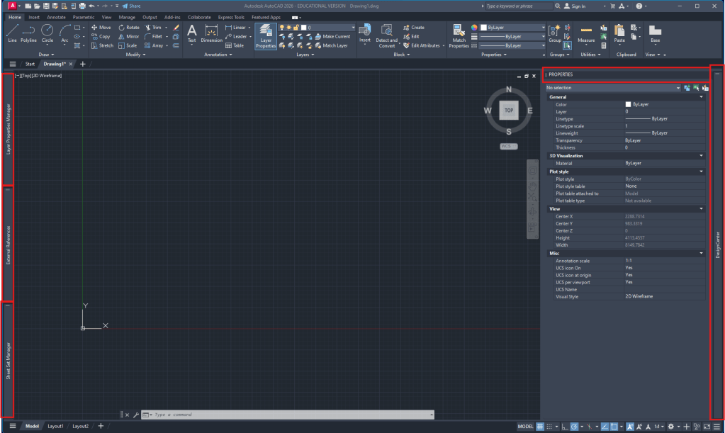
Autocad workspace setup:
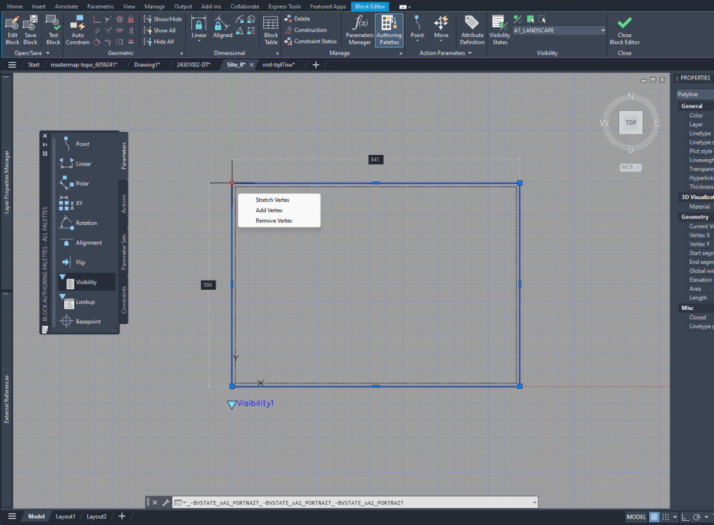
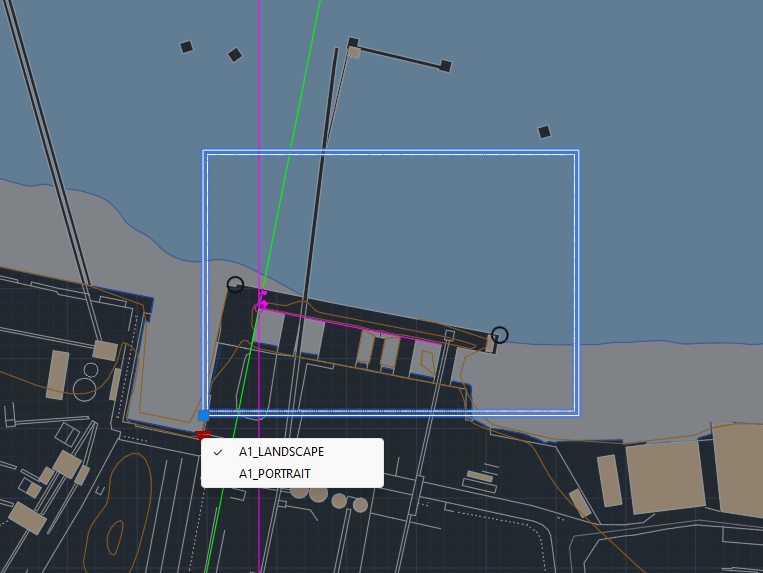
For the layout creation it’s helpful to see the outline in the Model Space. To do that I created a block of the size of the A1 layout and added Block creation
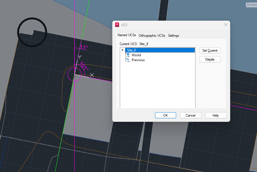
UCS creation for Site plan:
Alignment with existing buildings. ‘UCS‘ to create new. ‘ucsman‘ to give it a name.
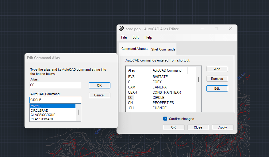
‘commandalias’ to manage/rearrange shortcuts
Week 2
Digimap
Due to the Digimap files having the scale in meters, we are always going to ‘scale‘ the drawings by 1000 to achieve the scale in mm that we will use in our drawings.
I realized that the standard unit-settings are often set to INCHES. So I use -dwgunits to set the units to MILIMETERS to prevent any issues with the layout/drawing later on.
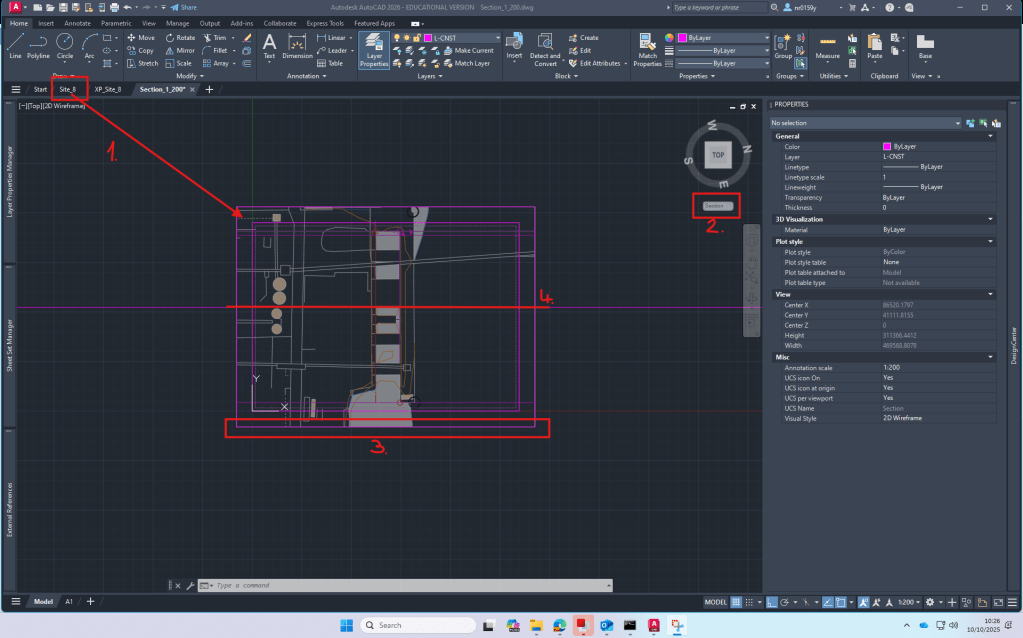
We spent most of the day looking at the important steps of drawing a Section.
For the section I XREF the downloaded and scaled file from digimap.
By using the file as an XREF I can:
make sure that the original file is not damaged in any way
work directly with my own layers without having to deal with the huge amount of layers from the digimap file
clip the xref on a certain cutout if I only need one part of the plan to be visible. (‘xclip’)
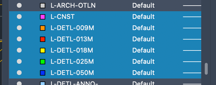
Layers
To be able to work with different lineweights I use the Layer setting I used to work with in practice.
The lineweight is always written in the layer-name and is also differenced by the colors of the layers.
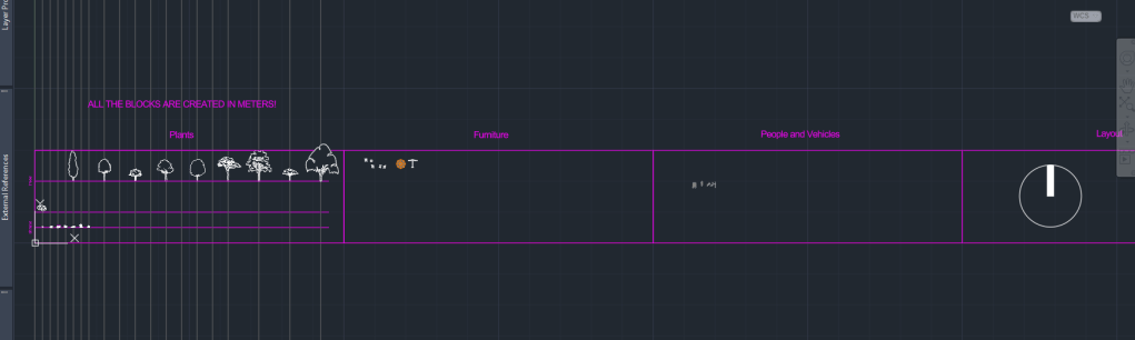
Besides the Section I decided to start my own block-library for future cad drawings with various objects, plants or annotation blocks.
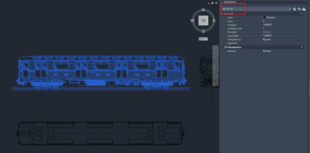
A big Problem with blocks, especially if they are downloaded from the Internet is the file size. Depending on the way they are created, blocks can exist out of hundereds, if not thousands of lines/vertexes, arcs or even ❗️splines❗️.
Example of a block, I downloaded from the web today, containing over 3000 Objects!
So I think it’s very important to clean up the blocks and minimize the amount of data that it contains. !Cleaning up a block can be a very time consuming action!
Due to some rather exhausting experiences with large file sizes (especially sections) and crashing computers, I became very picky when it comes to choosing blocks for my drawings. That’s why I only added few trees and other blocks to my library yet that are simple and cleaned up in a lot of hours of moving or deleting lines
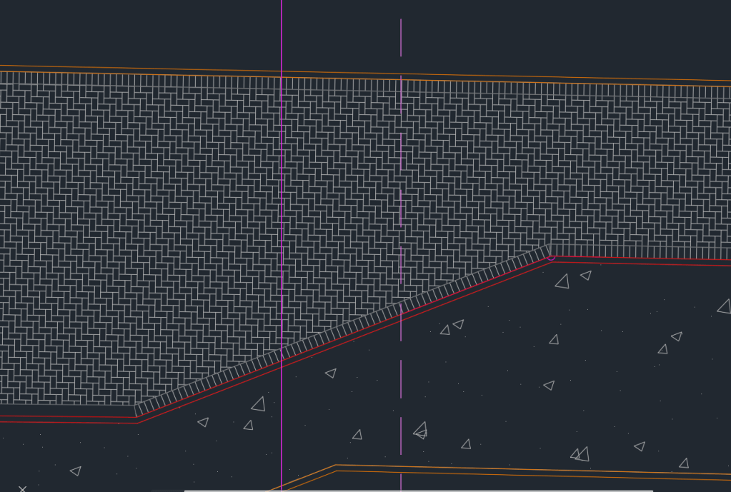
Today’s last AutoCAD introduction class was about practicing Hatching and adding Detailed information to our Project-Site Plans.
To get started I added the detailed Information of the pavers. However for our final Site Plan Layouts of the scale 1:200, it doesn’t make sense to add so much Detail to the Plan as it will only be visible as a black surface.
Part of the Stone Paving on my Site Plan
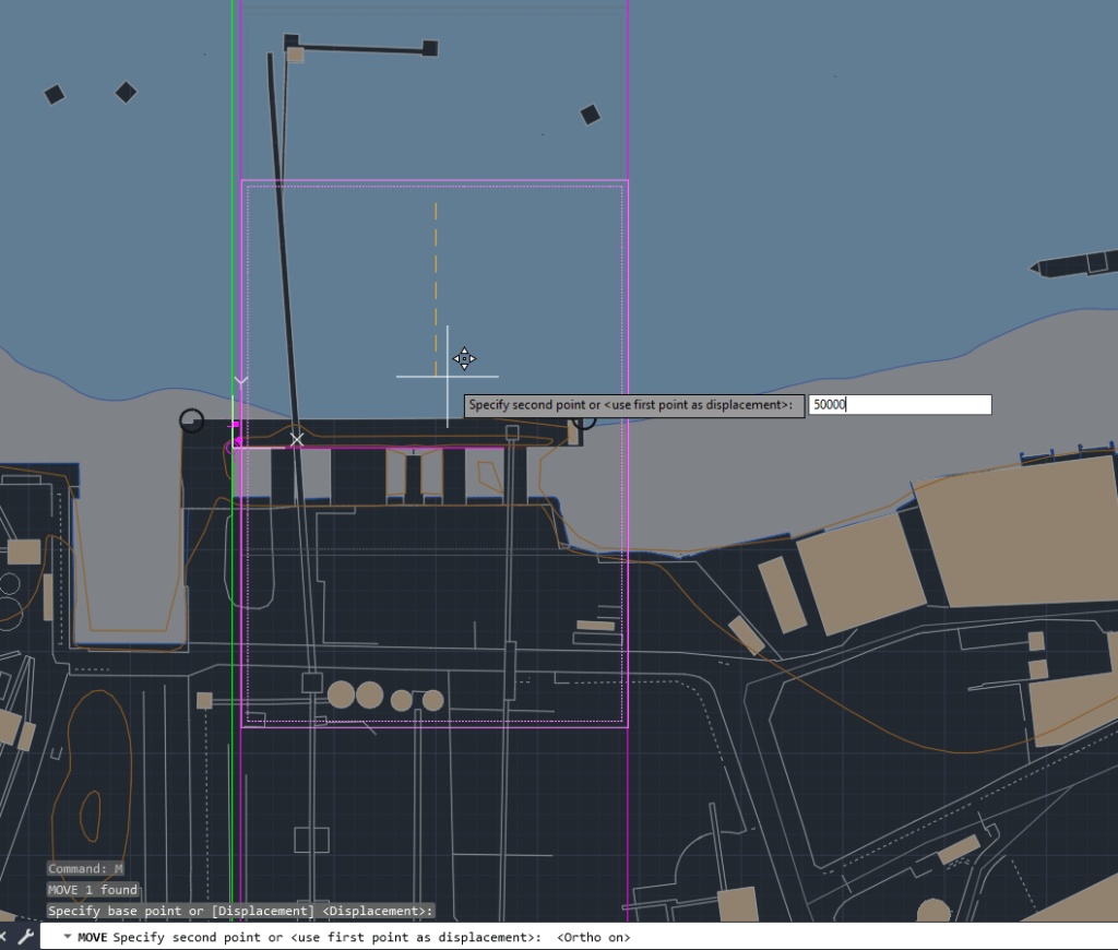
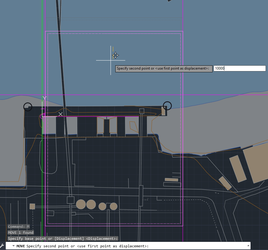
I also spent some time to move my Site to include the Thames Path and reduce the amount of water area, which is important for the further process of our Design Project.
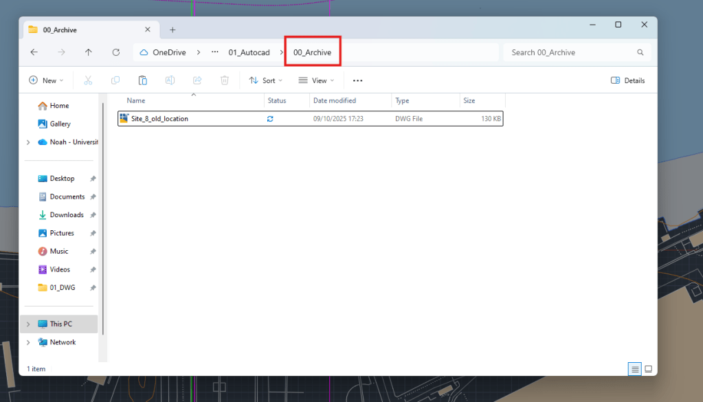
Archive of old Site Plan
Moving the site down (ortho)
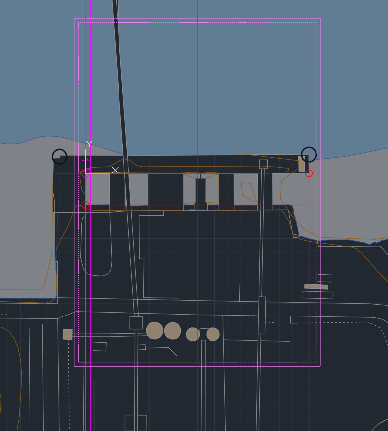
Final site location now includes the Tames Path and Part of the industrial site.
Setup 1:200 Section: XREF site plan -> create new UCS -> create clipping boundary for site plan -> Determine Section line.
Week 4
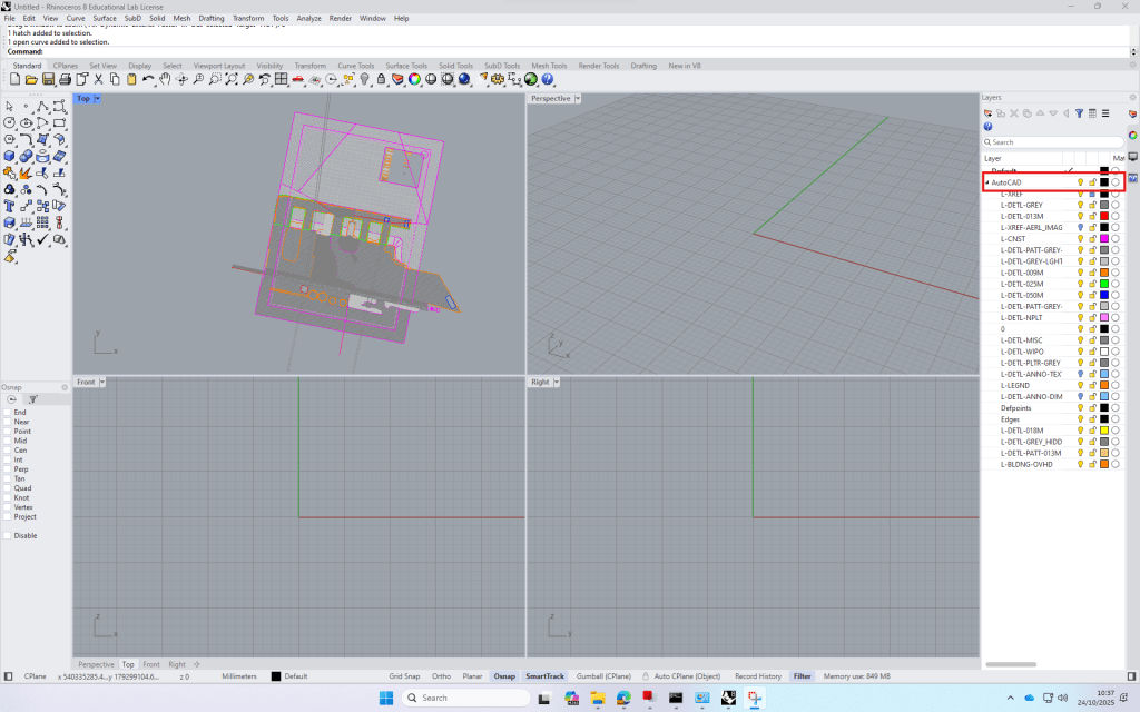
First class of Rhino
Rhino is a modelling software that works great with autoCAD. It’s easy to import your cad-plans and then visualize it. It’s also a good tool to build models from scratch.
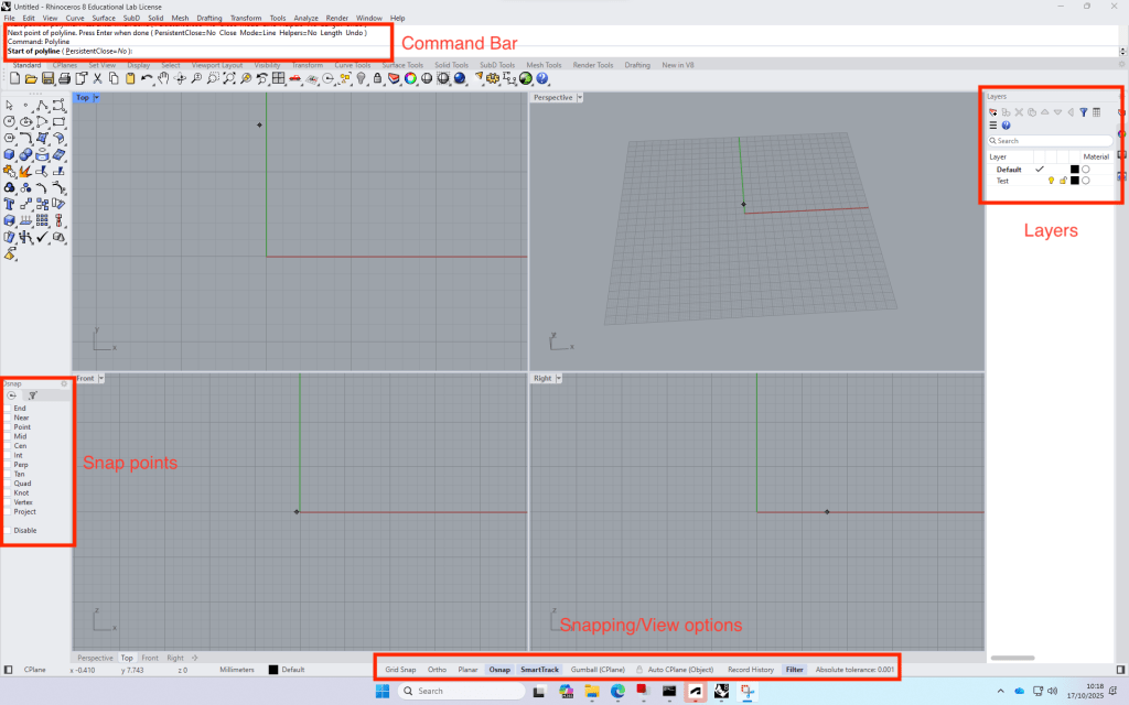
Build up: Four views -> can be opened by double clicking on the view name.
The commands are very similar to AutoCAD.
+ with the time, the program remembers your favourite commands
Test file process:
Create a rectangle (Top view)
Switch to Perspective view and type in “ExtrudeCrv”, then drag the midpoint of the line and type in the distance (height) of the block.
Copy the block and type in the required distance, repeat.
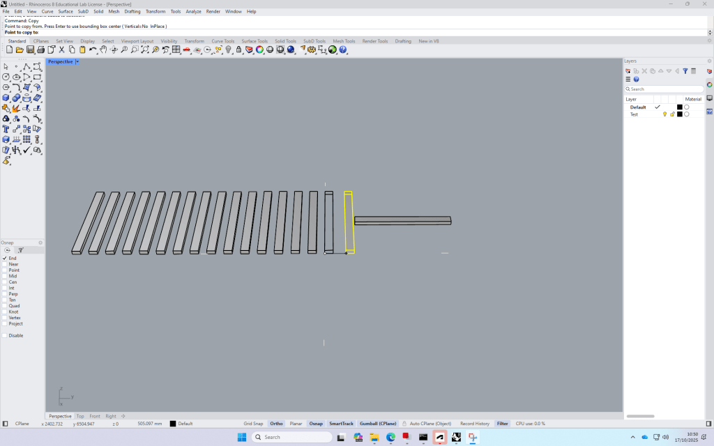
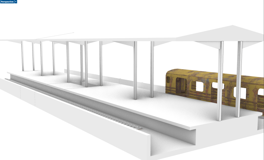
Test file “Train station”
How to create a Terrain model from digimap terrain downloads:
Download the required Area on Digimap
Open a new file and import the
Week 5
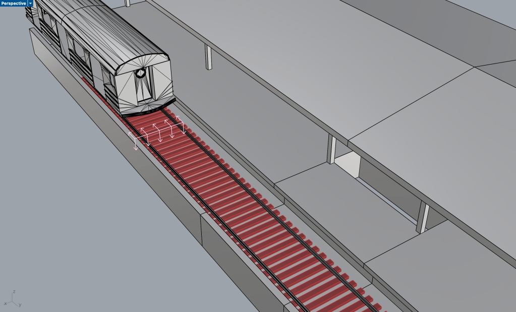
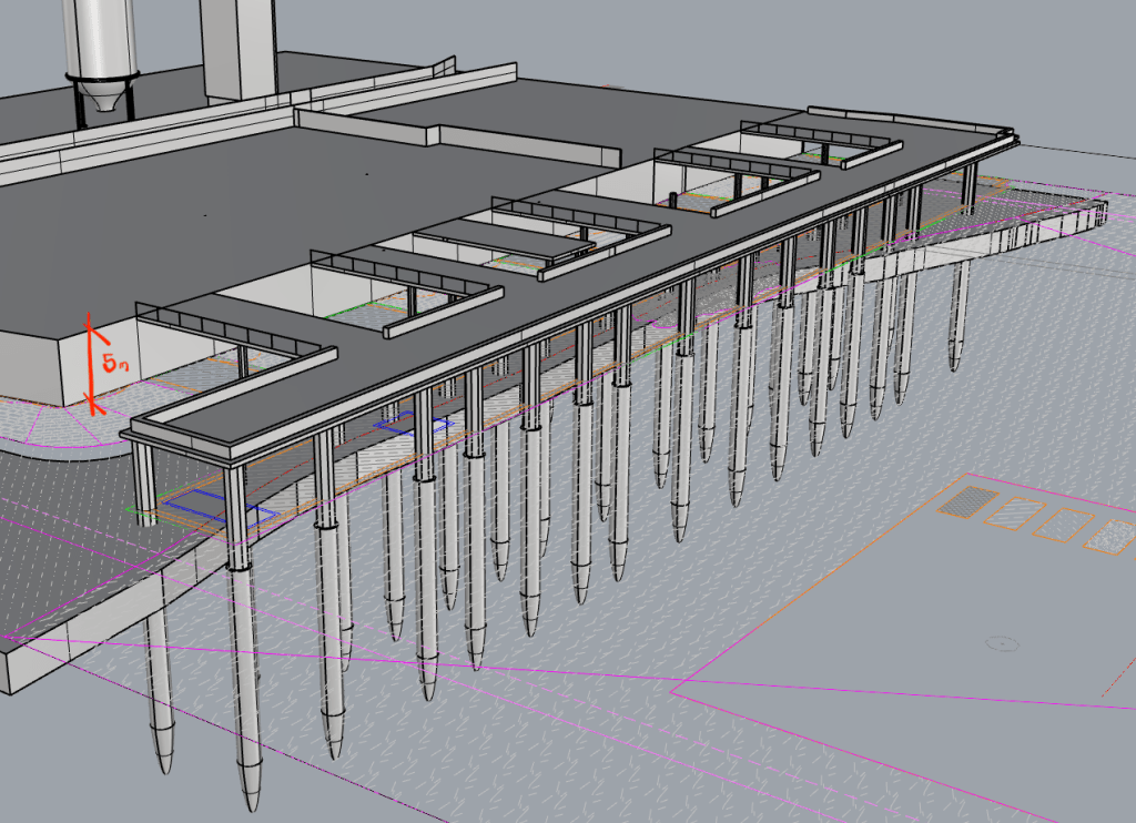
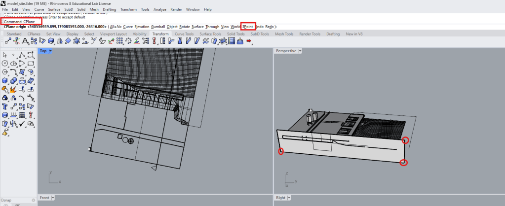
Today we started modelling our site in Rhino
To start off I imported my cad-site plan.
To extrude the cad lines, I first used command ‘project’ to bring them onto my model surface, which is 5 meters above ±0.00
For the river Platform I modeled one of the concrete poles and then copied it according to my investigation to get the whole substructure.
Week 6
Today we continued working on our rhino models.
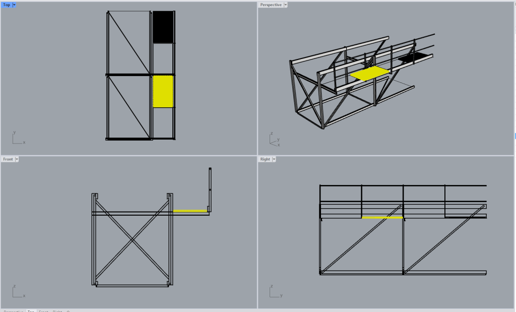
I spent most of the time modelling one of the conveyor belts on my site in detail.
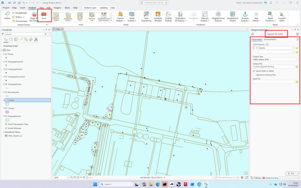
We also had an introduction on how get site information from ArcGIS
Digimap data can be downloaded and used directly in ArcGIS, where it is layered, analysed and visualised as part of a GIS workflow.
Export of tree data to cad.
Week 7
Today we had our first introduction in Illustrator.
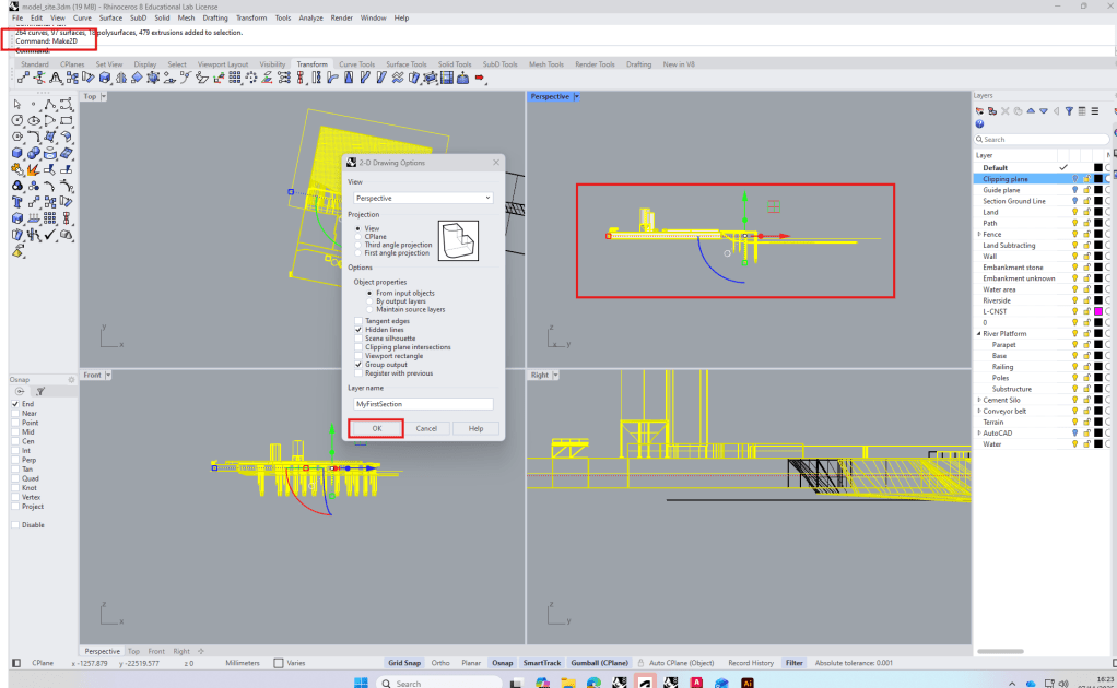
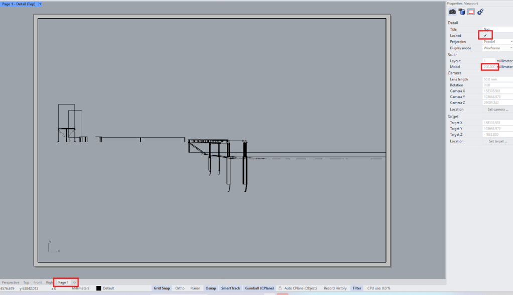
To start we looked at how to create a section in Rhino and export it to illustrator.
From the make2d file we create a new Layout and set the right scale in the properties window. (wrong settings here let to a lot of objects not being visible in the section).
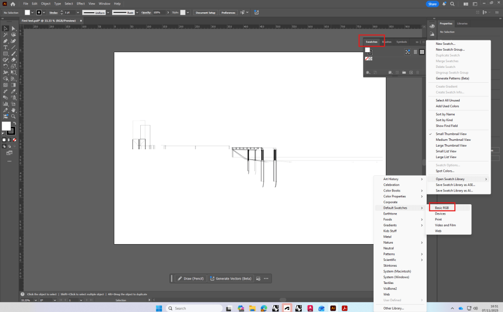
The exported pdf was then opened in Illustrator and the clipping mask released.
I had already created a template for my hand drawn design studio section, so I decided to finalize it and take it to illustrator afterwards for my ExCom submission.
Week 8
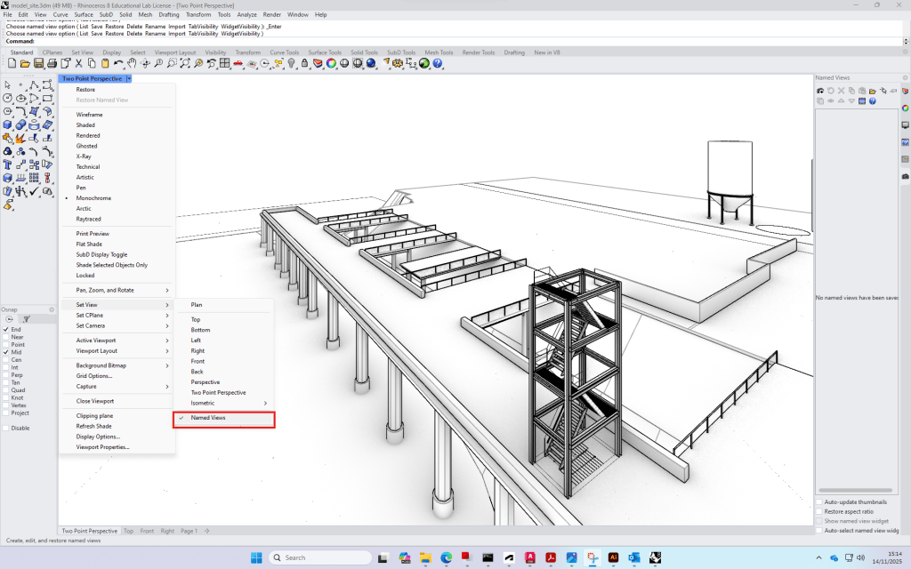
For the final submission we looked at how to set and export isometric/two point perspective/regular views.
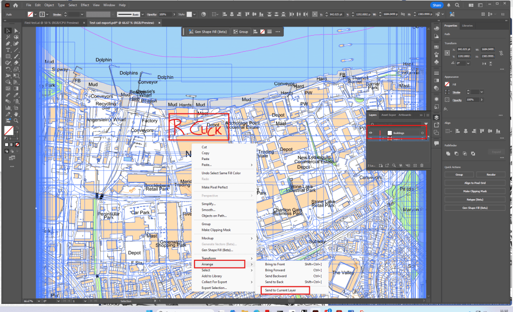
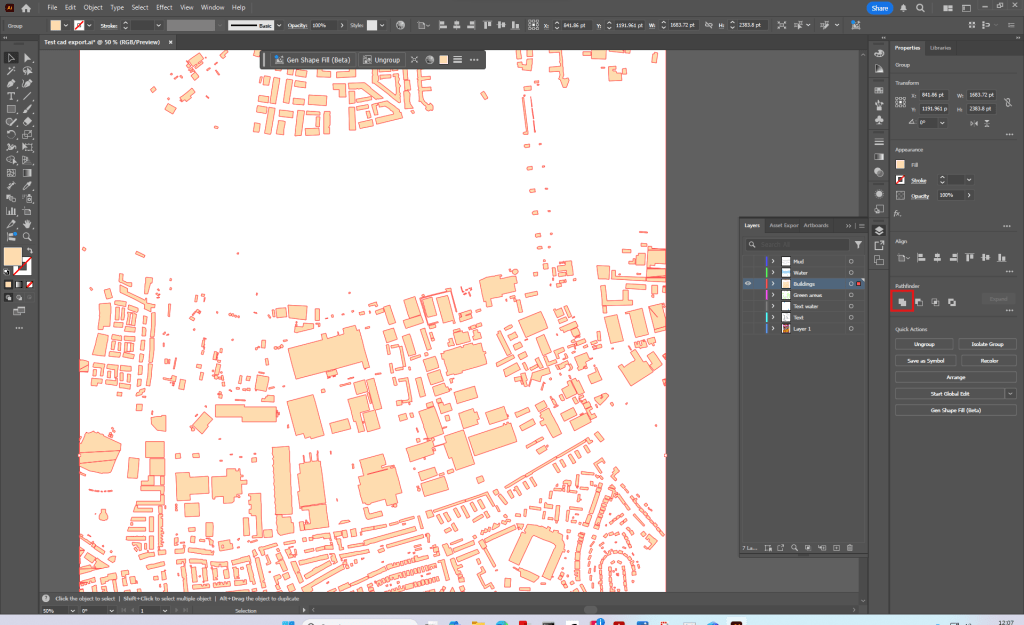
We then had further introductions to Illustrator.
Location map, separating hatches/lines and managing layers.
Week 9
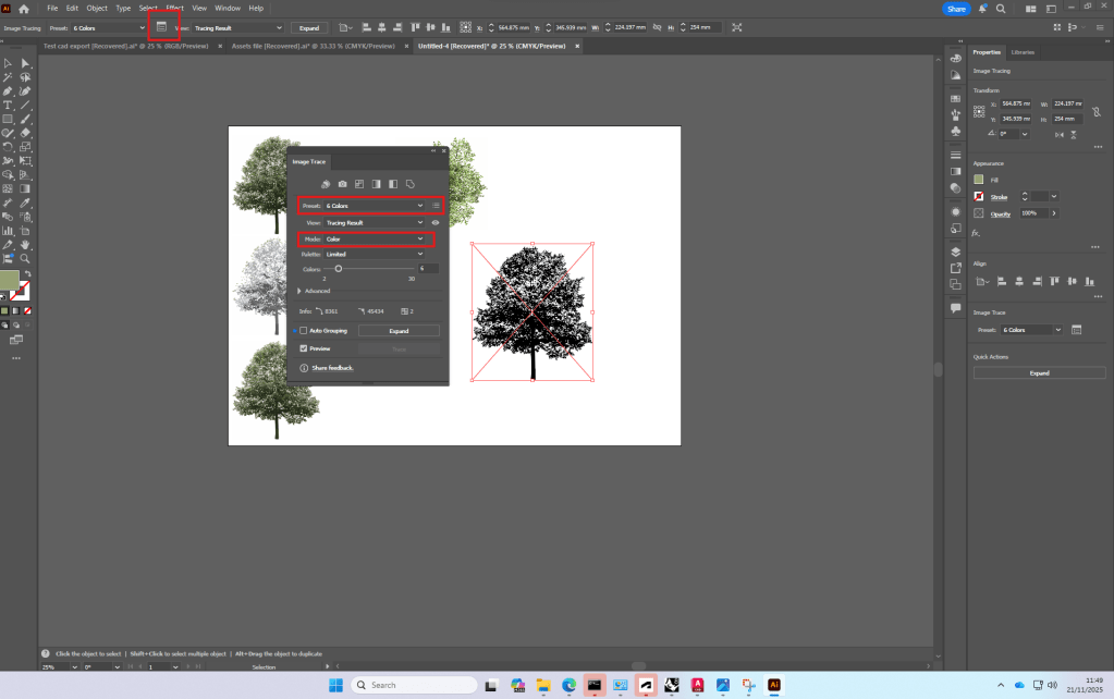
Using a png of a tree we looked at how to use image trace and make color adjustments in illustrator.
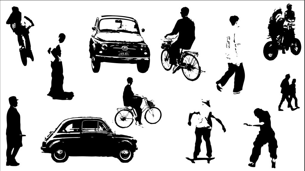
I then decided to use image trace to create people for sections, using photographs I took. This could give future section or perspective drawings nice personal touch.
Week 10
Photoshop introduction/exploration of ai tools
Due to a lot of Plant technology-work in photoshop I was already familiar with most of the photoshop tools.
We also had a quick introduction to
Week 11+12
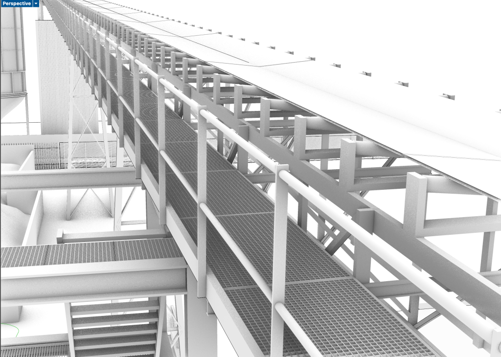
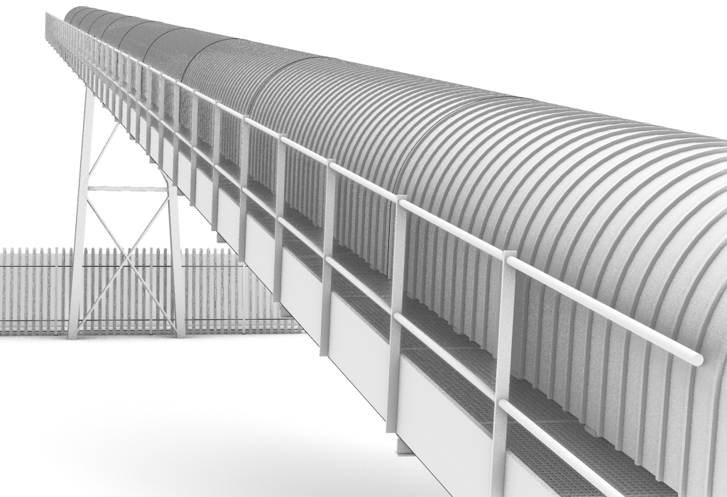
I used the last two lectures to add more detail to my rhino model and complete it before exporting the isometric and the views
Conveyor belt+access structure
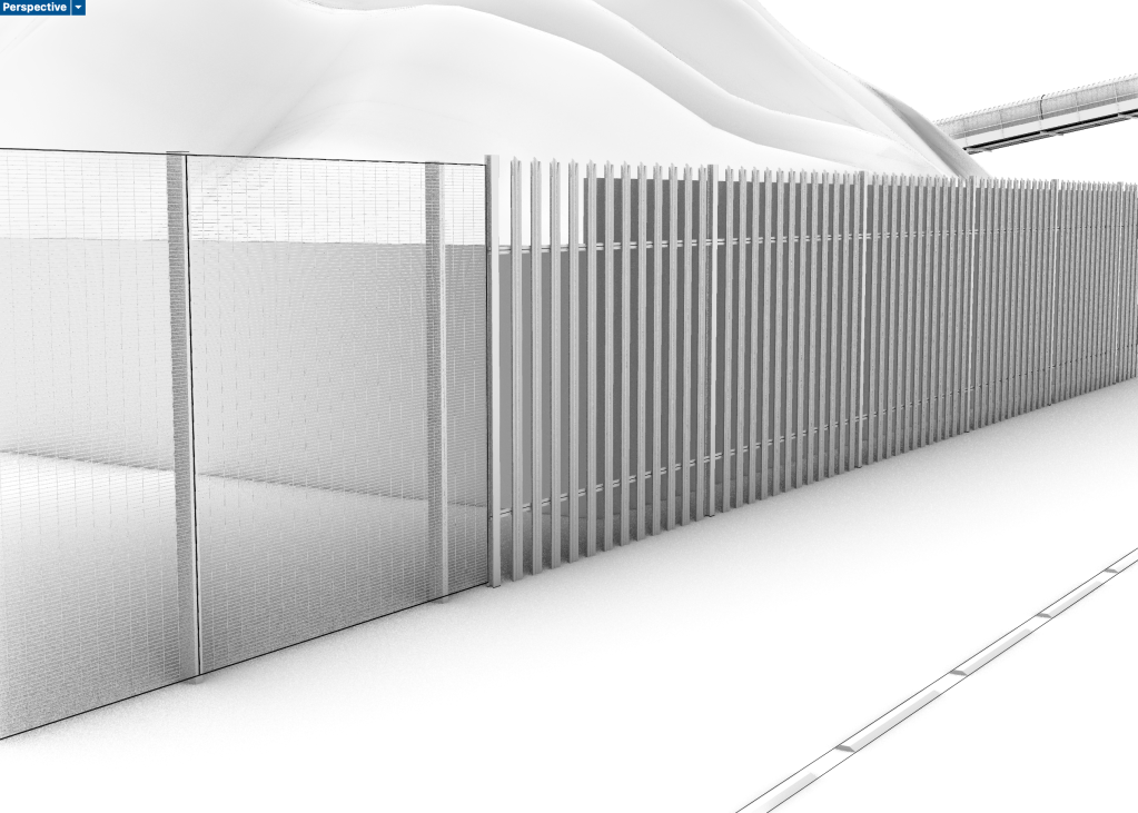
Fencing
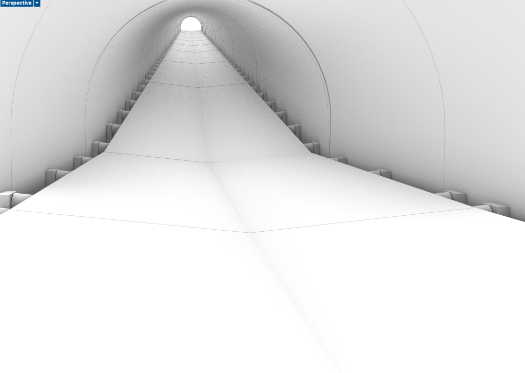
Second conveyor belt on site
When creating the views for my export I realised that a lot of the detailed information is not visible, so I could have kept it more simple in some areas and only focus on more detail in the visible area -> set views earlier.
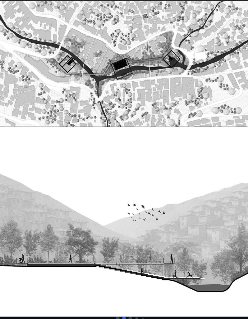
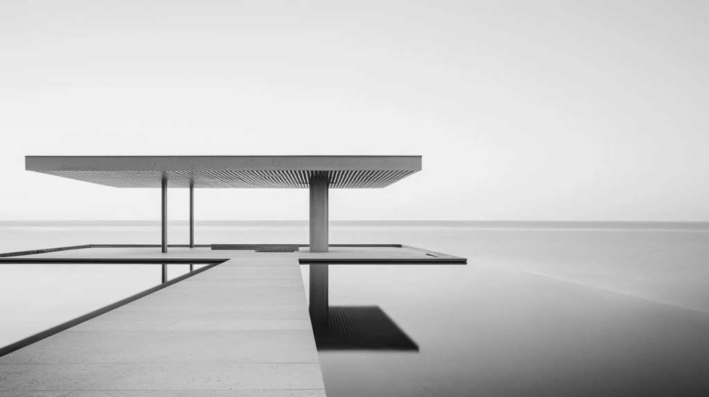
While looking for inspiration for representation in llustrator and Photoshop I came across multiple approaches that mainly used black and white or had a very minimalistic use of color.
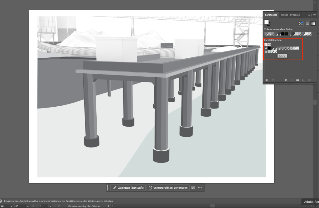
Screenshot
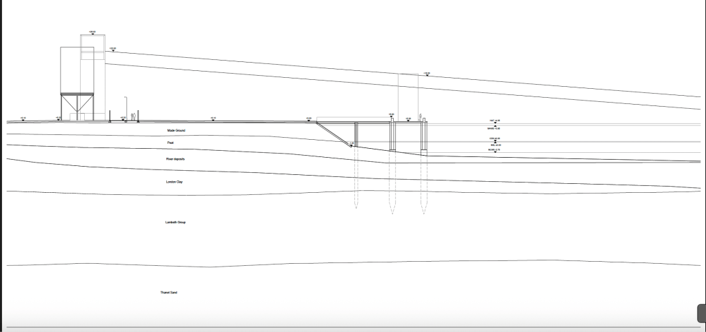
So I decided to try out a similar approach, only using different grey tones in illustrator, except one slight green tone to make the water surfaces stand out.
In that way, the industrial feeling of the site and the dominance of concrete could be represented in the drawings. The feeling should be communicated by textures instead of colors.
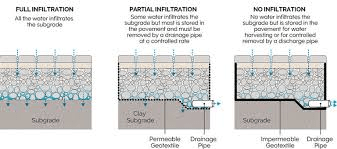
Permeable Modular Pavement, Steve Burton from Steintec
A first step for permeable surfaces in a project should be to think about how much water actually needs to run through the surface. Different requirements need different levels of drainage/permeability.
To ensure permeability, mortar joints need to be wide enough
Climate change factor:
Whaterver the Volume of Rainfall is, you add 40% to plan for the future and consider climate change.
Another key aspect of perm surfaces is pollution control:
Inflitration rate:
Total surface area : area of joints x permeability rate
-> how much water goes through 1m3 of the material
The infiltration rate gets lower after a few years. After 10-20 years it’s only about 10% of the original rate. So we should aim for a bigger infiltration rate that will last as long as possible.
Urban Landscaping with natural Stone, Lisa and Dave from FMDC
The Stone Federation of Great Britain promotes natural stone.
Natural stone is aesthetically better than alteratives, gives a higher quality feel, is a natural product -> less embodied carbon.
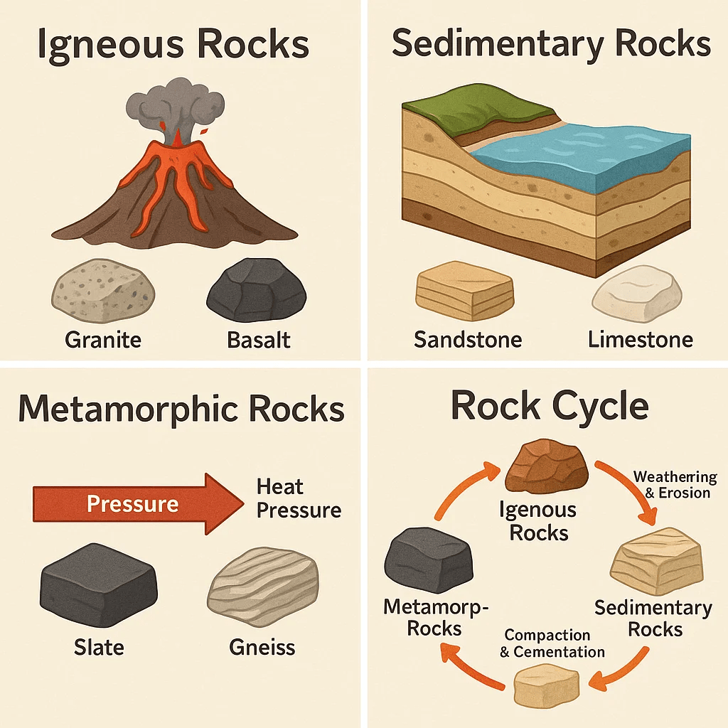
Geology
How stones were formed in their geological process has a big impact on their characteristics and on how well they perform in different situations.
Porosity:
Granite (Igneous): 0.1 – 0.5%
Sandstone (Sedimentary): 10-20%
“You need to be armed with the knowledge needed to identify a stone, which might be praised as something it is not by manufacturers.” -> if the name of the stone isn’t protected, other stones can be sold under the same name!
-> CE marking is a legal requirement in the UK, which means that the contractor needs to deliver the material according to the CE certification.
How to select the right stone:
Color -> stone type -> suitability for purpose -> local context -> planning guidelines -> compability
No two stones (even within the same group) will be the same. Surface finishes and color variations always play a role in the stone selection process.
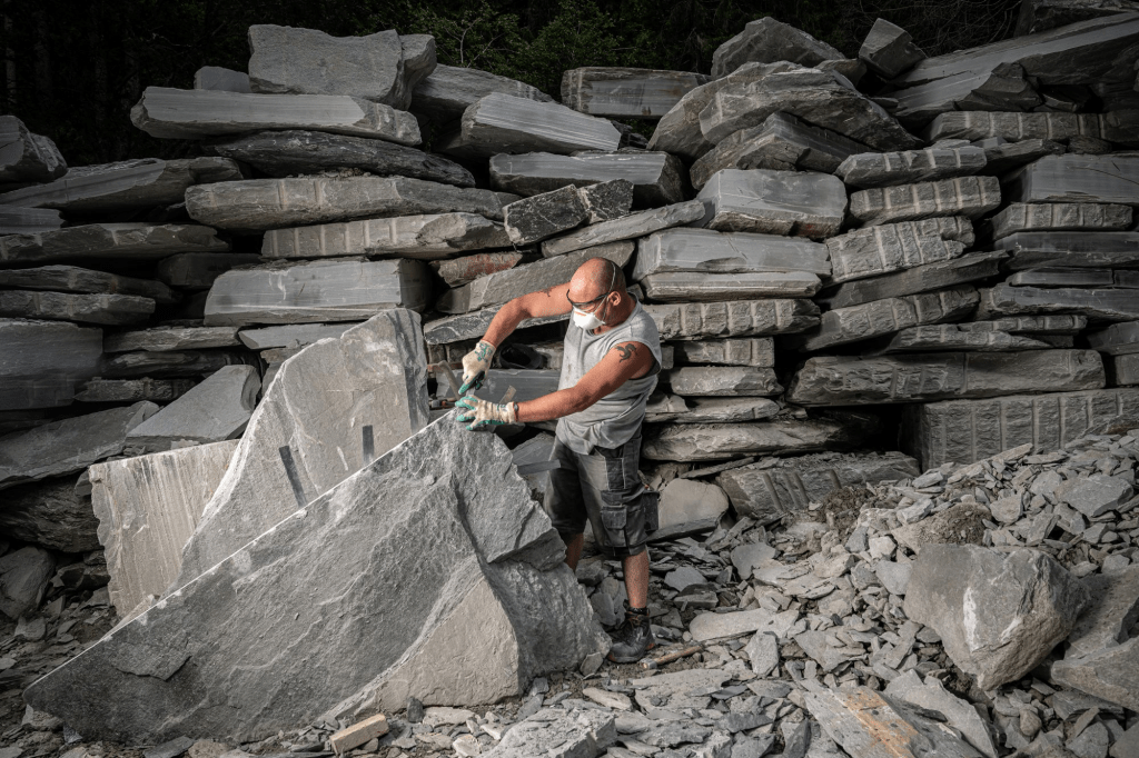
Stone samples are not what you want to select your stone based on. It’s better to see actual examples and visit the quarry and factory to see where the stone actually comes from, how it is produced, how the quality standards are, etc.
Testing the stone on how it reacts to different impacts like salt, weight, etc. can be very important.
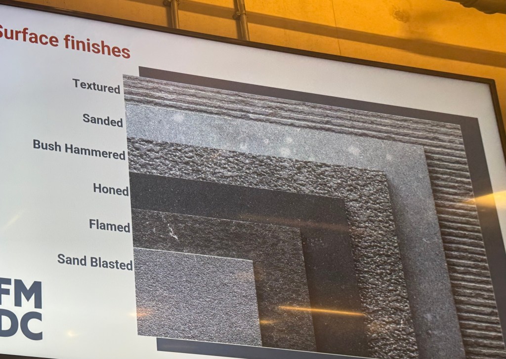
Surface finishes:
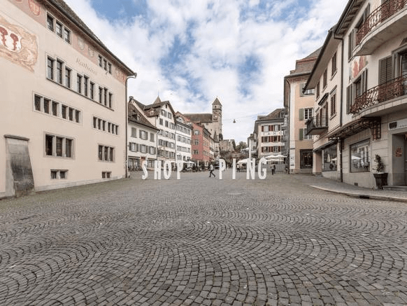
Other than in the UK, Quarzite is used very often for public spaces in Switzerland.
Valser Quartzite is a high quality Stone, originating in Switzerland.
Landscape Lighting Fundamentials, Paul from LIGHT BUREAU
Lighting in it’s natural form and in combination with photography and in architecture as well as landscapes is a very interesting topic.
Exteriors unlike interiors
hard to control
no “ceiling” -> zero reflectance
hostile environments
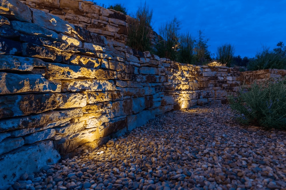
Lighting can highlight materiality and textures
Daylight
Thinking about shadows and light/heat can be essential in planning processes.
Shadow study
Colour appearance
Using different colour temeratures makes a big difference on the feeling of a space.
Office spaces: 4000K -> colder light keeps people awake
Restaurants: 2000K-3000K -> create a cozy environment
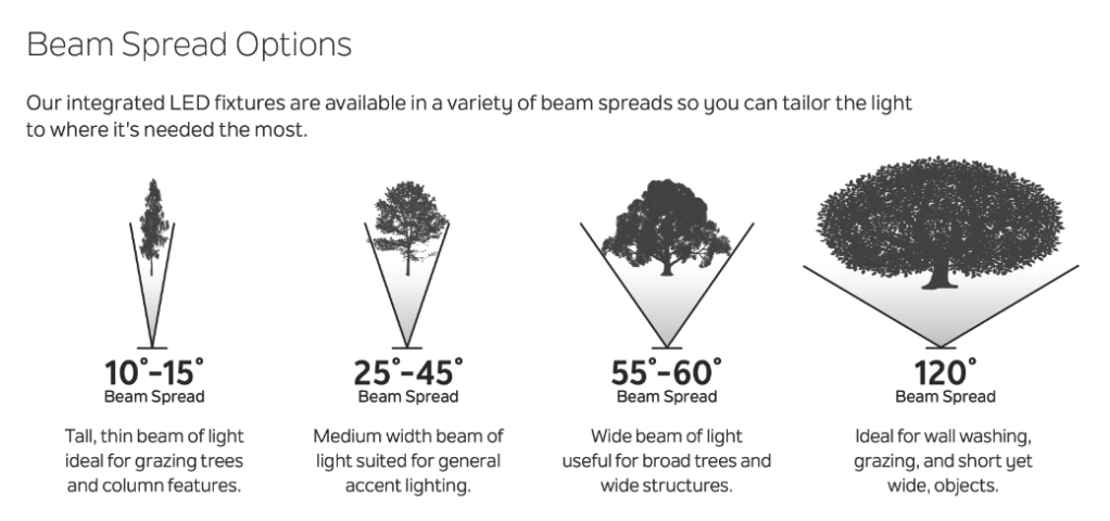
Technical aspects
Thinking about the right beam angle and the right placement of the light source is essential for a successful project.
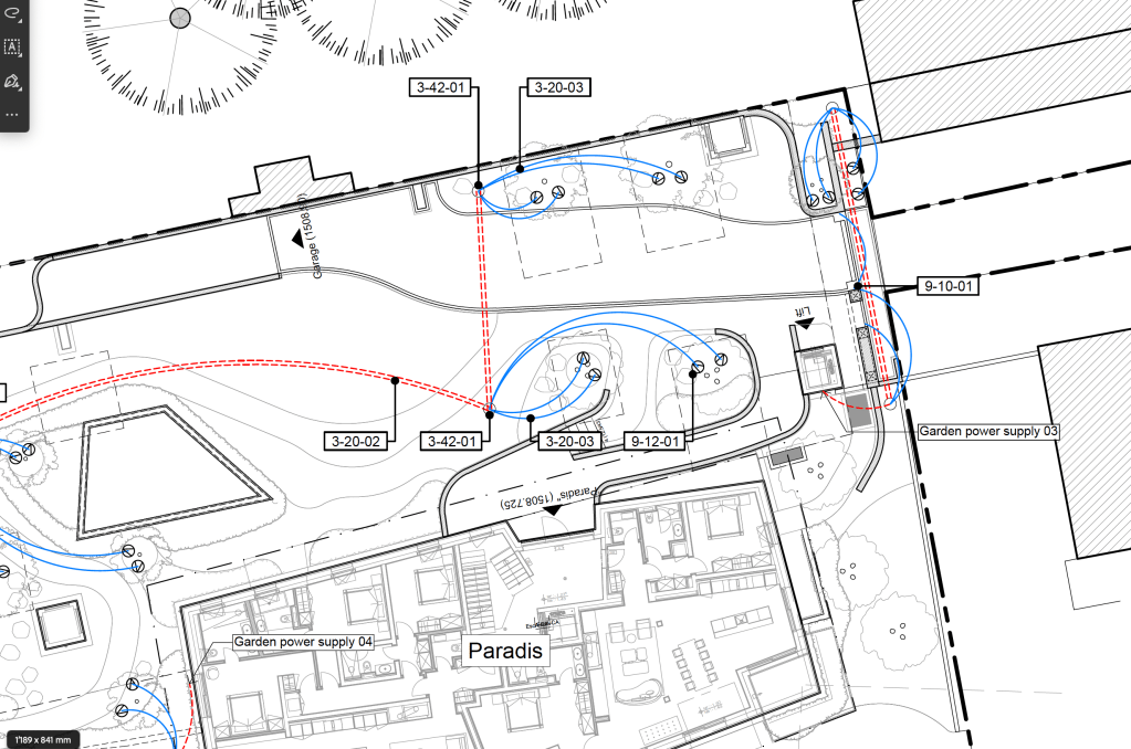
Section of a lighting concept plan I created in practice, before it was handed over to a lighting specialist.
The goal of this lighting concept was to make a proposal of which areas and trees should be highlighted and to think about how the cable laying could be done to provide the electricity from the electrical connections on site.
The plan was then discussed and handed over to a lighting specialist to integrate his professional knowledge to create a final lighting concept and detailed plans.
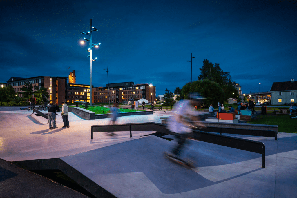
The range of case studies that Paul impressively showed us how much a thought through lighting concept can improve and affect the visual quality and feeling of a project.
Success in the Art of Pavement Construction, Steve Burton and Phil Critchton from Steintec
Planting and hardscape work close together and often lead to very technical planning processes.
The arch shaped pattern of pavement have a structural function. If the path has a slope, the arches are created in the opposite way (up the hill) to take on the loads of vehicles that use the road.
Unlike in Switzerland and other parts of Europe, not many of the arch shaped patterns exist in the UK anymore. Mainly because the industrial. revolution and development of “better” and more “fashionable” solutions.
Arch-shaped paving in my hometown
Paving starts suffering from different issues/impacts over time.
Cuases of failure can be:
Bad design
Wrong methods -> workmanship issues
To prevent workmanship issues we have know that we need to make sure that appropriate methods are used on site!
Landscape Architects usually can refer to guidance of manufacturers on. how to use materials correctly on site.
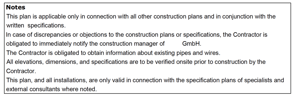
Extract of a Construction Plan with specific directions for the contractor
Pavement Design
We have to make sure that the pavement build ups and materials are defined, correct and implementable on site.
Sustainability
longevity
need of maintenance
reusability
Bound vs. unbound construction
Bound construction only fails once. So it should always be planned to be able to take slightly more than the max. required loads.
Unbound construction gets worn down when heavily used but it dies’t fail right away
Unbound materials in Switzerland: would be good to start researching or contacting companies that I’m familiar with back in Switzerland to include some of their approaches in my design/planning processes in the UK.
3 types of paving element
Full depth sets -> moving vehicles put force in the moving direction and downwards, which creates a rotational effect.
Slabs -> Force downwards on one side and “counteraction” on the other side
Shallow sets -> both of the above combined
Movement joints are always important to absorb material expansions/compressions
Moisture
Moisture can bring range of problems and damages to pavings: Frost damage/damage through temperature changes, permanent water marks
Permeable material underneath the paving is essential to prevent damages caused by moisture. Using bigger grained mortar instead of sand/cement mortar can increase permeability
Importance of standing by your specification
Value engineering -> You choose the right product to meet the requirenments based on performance
The contractor chooses the material based on costs/profit.
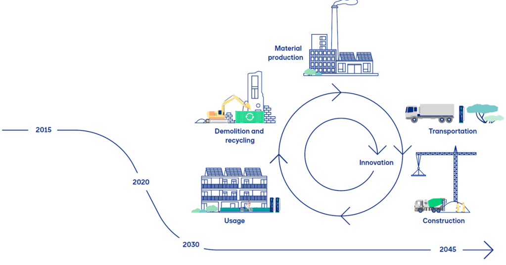
Resiliance (resistance through creation of spaces, water management, biodiversity improvements)
Transformation (accept that transformation is needed and fully adapt to the changes -> example: rising sea level causes flooding of rivers => fresh water turns into salt water)
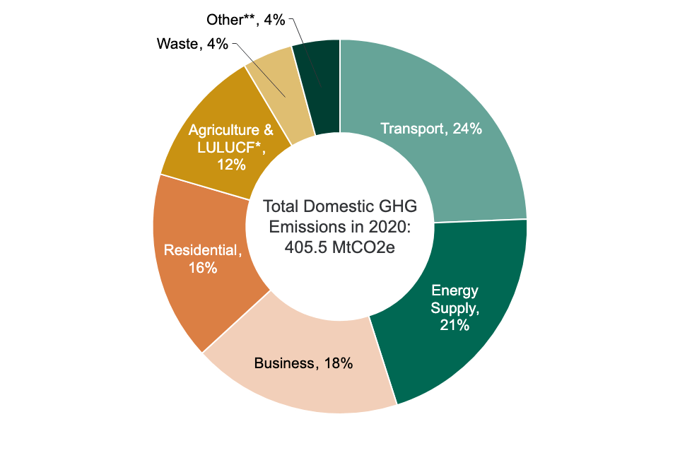
Climate change mitigation
Reducing greenhouse gas emissions.
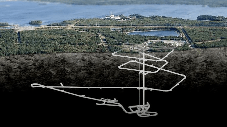
The UK has made a commitment to reach net-zero GHG emissions by 2050.
At the moment the UK generates about 15% of its electricity from nuclear power. Nuclear power and the handling of nuclear waste remains a widely discussed topic.
Proposed nuclear waste tomb in Finland.
Carbon footprint
Carbon footprints measure the total greenhouse emissions caused directly and indirectly by a person, event or product.
It measures in tonnes of carbon dioxide equivalent.
Steel and concrete are materials that produce a lot of carbon dioxide.
Reduction of the carbon footprint:
The use of recycled products can reduce the emissions.
Trees of course have a great impact on reducing CO2 emissions.
Sustainable transport
Sustainable drainage
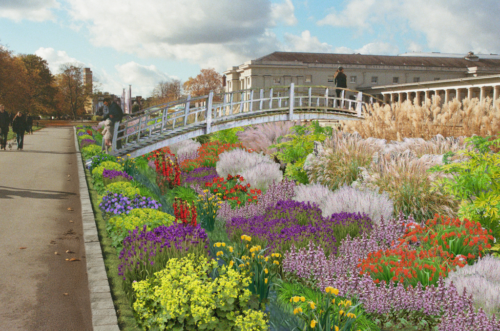
Rain gardens are effective methods of surface water management.
Substrates with recycled products
Inclusion of rooftops -> especially in highly urbanized areas, the use of rooftops can be a good option to compensate lost green spaces
RIBA Plan of Work
The RIBA Plan of Work is a document that outlines all stages in the planning, design and building process, from conception to completion on site. It is the most common document used in the UK to describe the stages in construction projects.
The Landscape and Carbon report by the Landscape Institute provides a lot of information regarding today’s topic. I will definitely come back to it for my work in future projects.
AutoDesk civil 3d is a software to use for planning height management on a site. During my time in practice it was often used to
We need to be aware of flood. risk, time based measurement. And the probability of the one in a hundred year storm happening at any time.
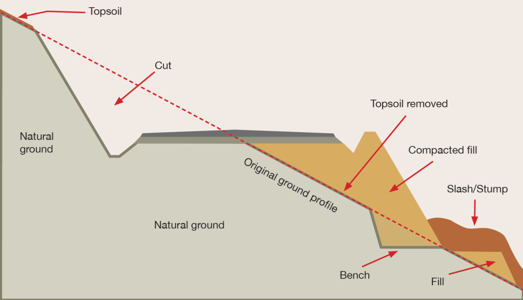
Earthworks
Excavations, Top soil is removed, recountouring bel
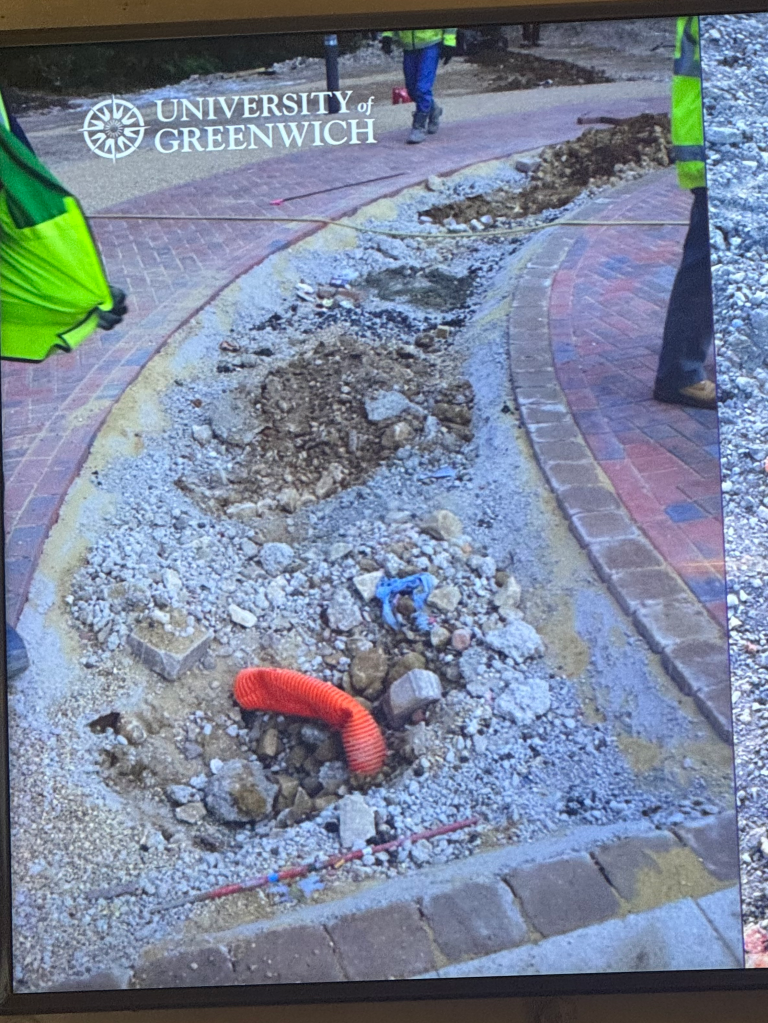
Positions of pipes always need to be included in planning processes
Bulking factor / Shrinkage factor ->
Compaction -> Proctor test
If a CBR of 5% or more is measured, standard build ups can be carried out.
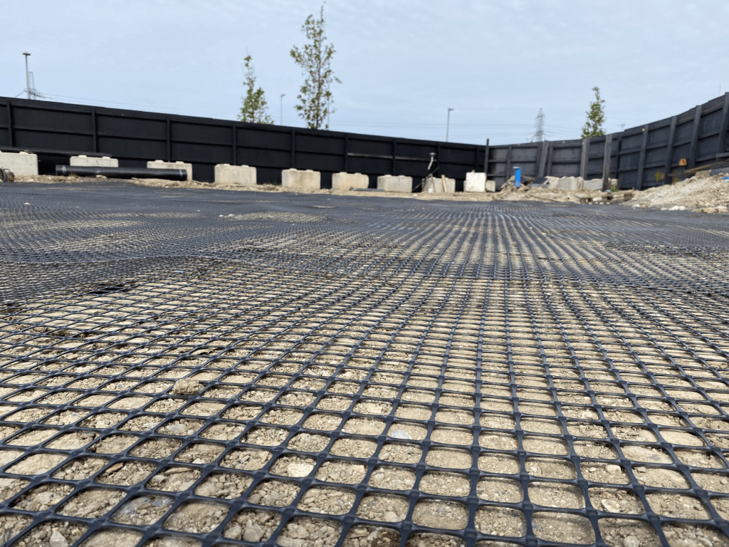
Geogrids can be very effective and will provide an additional level of support insted of bringing in capping on top of the subgrade.
Another way of aubgrade improvement can be using lime/cement treatment.
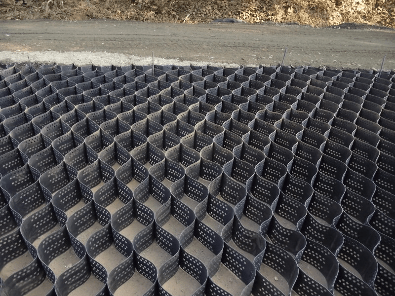
The amount of pressure on the ground can be reduced using cellular confinement systems
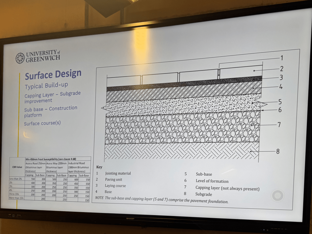
Standard build-up example
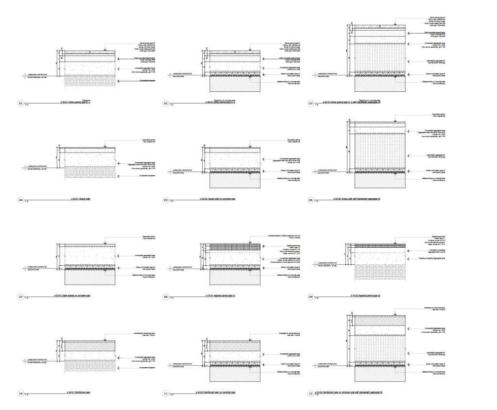
Range of standard details I planned for a project in Switzerland.
Flood zones 1-4
Be aware that soil can vary a lot and sites can have different soil types.
All the different types should be tested
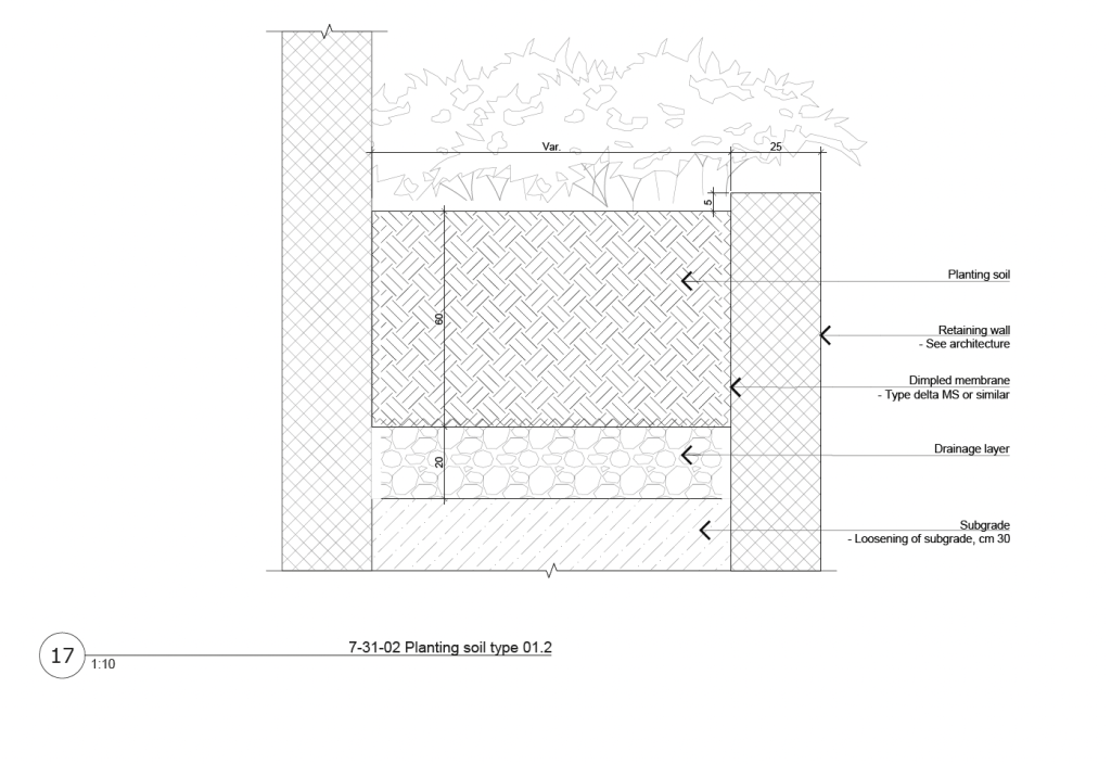
Planting areas and soil depths always have to be planned carefully and coordinated with the contractor.
Example of a planned shrub area. Visible not enough depth for soil.
In cases like that it’s always important to think about the planting details and provide the right drawings as well as communicating with the contractors to make sure that it will be carried out correctly.
Example of a detailplan for similar situation (planting between two retaining walls)
Soil contamination
Sites always have to be investigated carefully on noticeable characteristics:
Unpleasant smells
Striking colors or tints
Chemical waste or other pollutants
Signs of heat
Soil contamination is a big issue that I haven’t come across in the extend as I worked in practice in Switzerland.
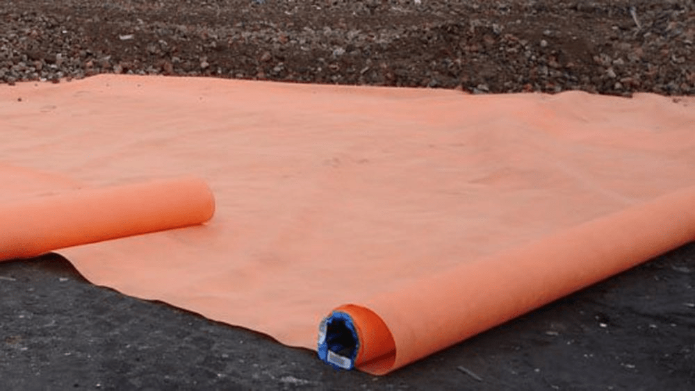
A marker layer can be laid over the contaminated soil and then be covered by 600mm of subsoil and 400mm of topsoil.
Another form of conamination:
The japanese knutweed crowds out native plants, erodes riverbanks, and can cause structural damage to buildings by growing through foundations, walls, and paving.
How to determine the amount of soil for a tree
If we know the area occupied by the tree canopy (Crown projection), we multiply it with the leaf area index (gets us the leaf volume). We then have to include the evaporation rate (can be looked up from meteorological date) and the correction factor (calculated from research: 20%) index. That gives us the daily tree water use.
Daily water use x rainfall frequency : available water holding capacity of the soil = a realistic soil volume
Example:
Tree with a 3m radius -> around 28m2
28m2 x 5 (leaf area index) x 5mm (evaporation rate) x = 140 (daily ater use)
140 x 10 d (rainfall frequency) : 0.13 (available water holding capacity) = 10.8m3.
Gardens on a substructure (Roofgardens or Gardens with a basement underneath
The conversations between Architect, Structural Engineer and Landscape Architect are always important!
Fundamentals of Structural Engineering:
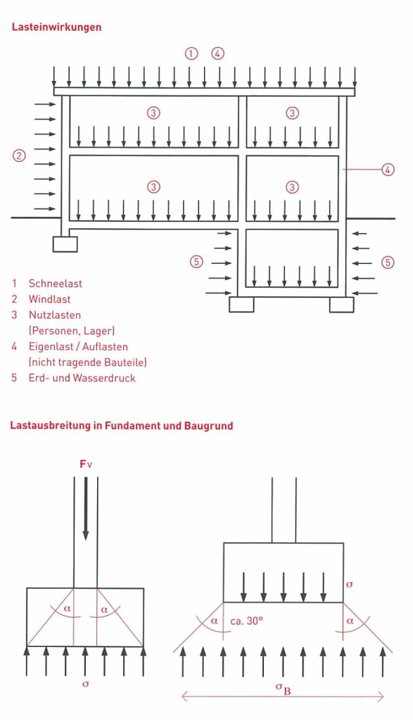
Transfer of load to the ground -> Load Path
Different Load Effects of a Building (Excerpt from a Swiss construction training manual)
History of Structural Engineering
My personal favourite example of historical structural engineering, the Pantheon in Rome (125 AD)
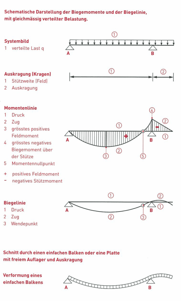
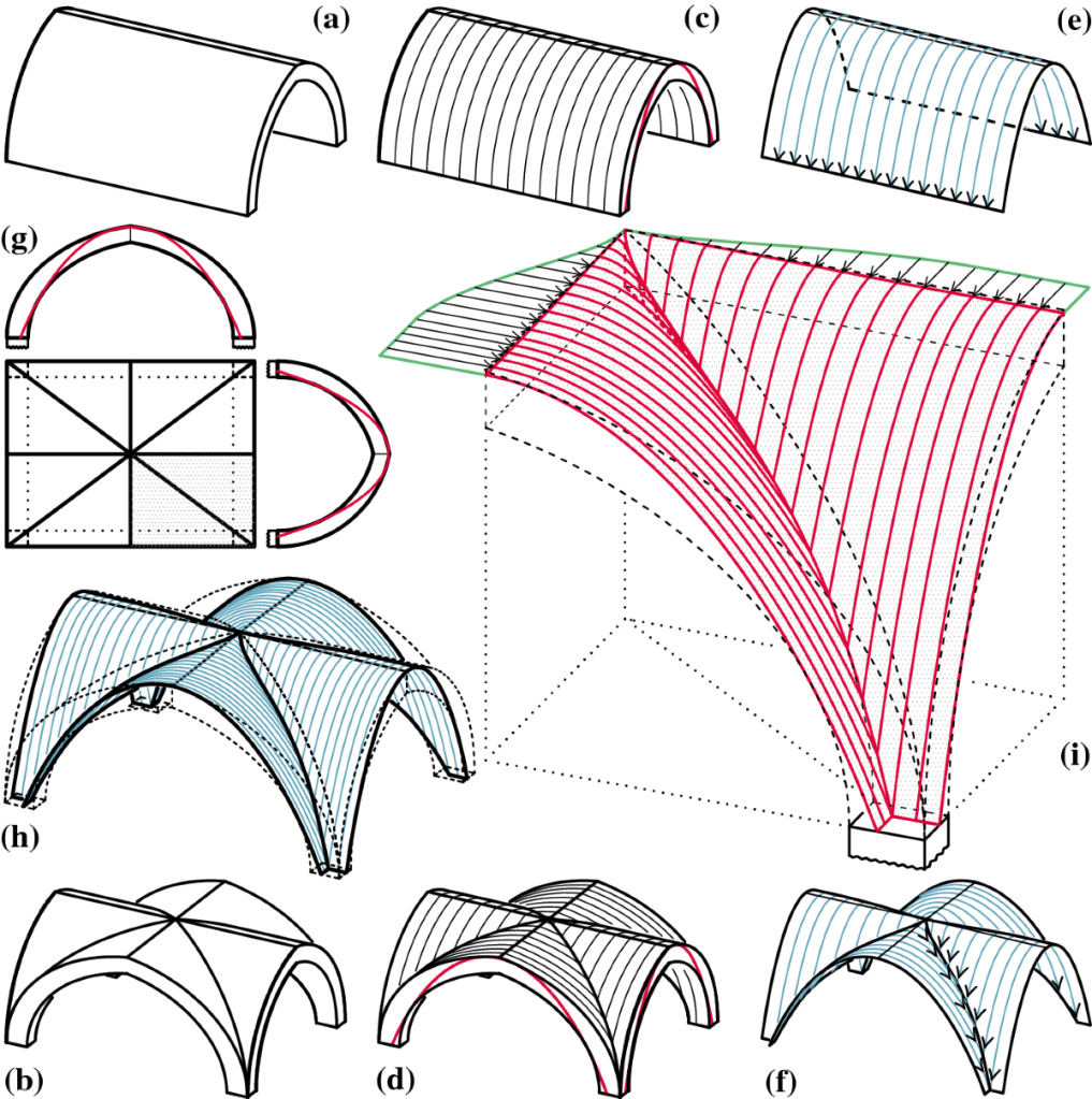
Vaults
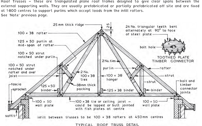
Timber Truss
Iron
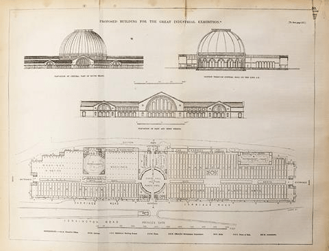
Chrystal Palace, 1850s
Concrete
+ compression
– tension (unless reinforced)
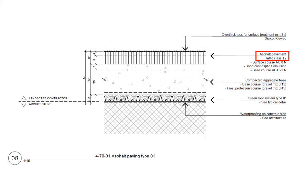
It’s always important to think about the use of the different Pavements regarding the loads that it has to hold up to (traffic classes)
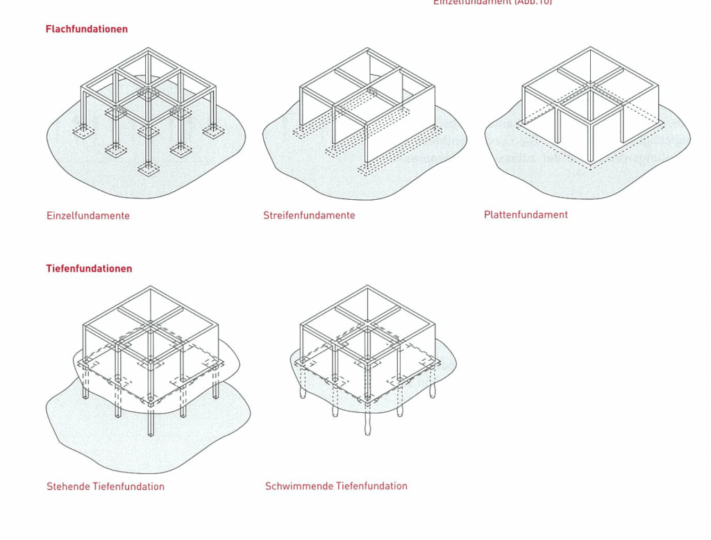
Fundations
Californian bearing ratio (CBR), parameter for determining the appropriate thickness of flexible pavements -> 5%
As long as the ground has a CBR of 5% or more, we will be fine!
Types of Foundation (Swiss construction training manual)
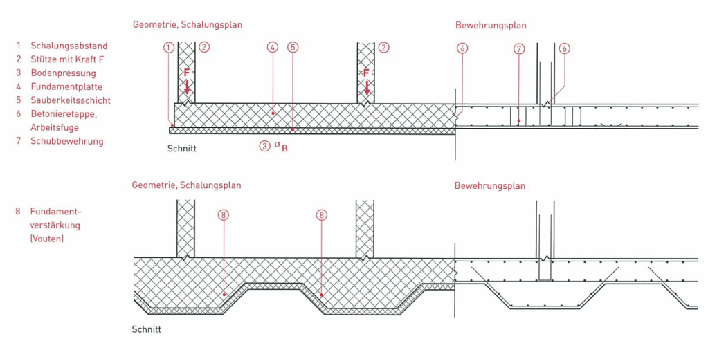
Raft foundation Section of Geometry and Formwork plan (Swiss construction training manual)
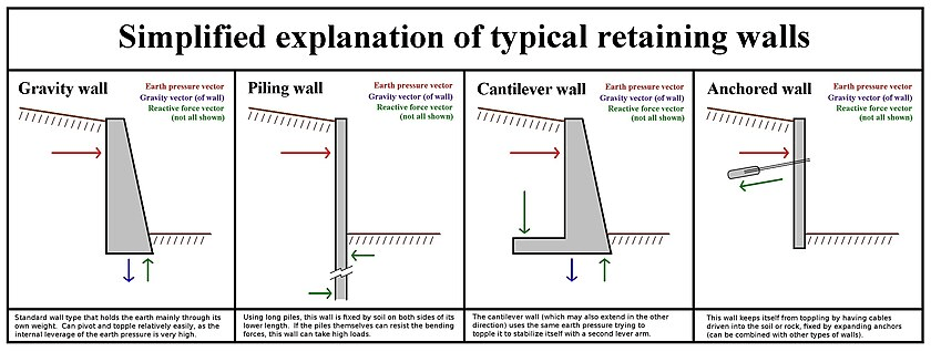
Retaining Walls
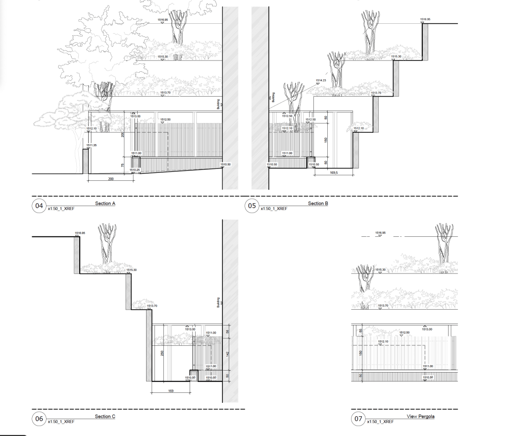
Example of the use of retaining walls in practice:
In this project we had to deal with minimal space and a big height difference close to the building wall, including a pathway alongside the building.
Draft of four views/sections
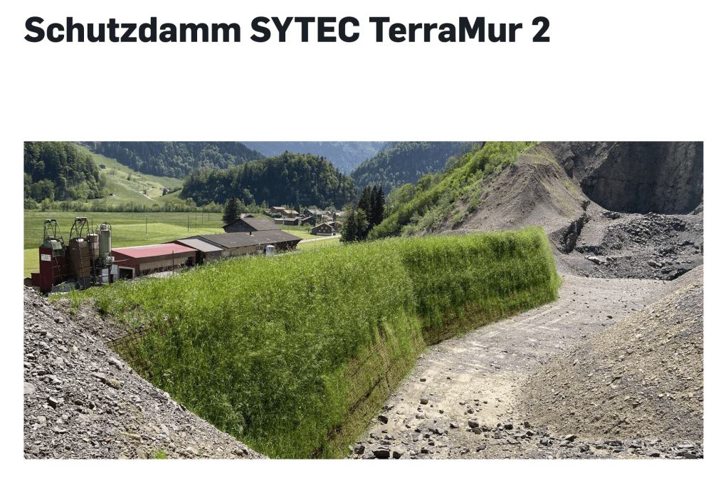
The TerraMur System is a very interesting variation of retaining walls, especially used as a protective dam for very steep embankments. It can also include greening.
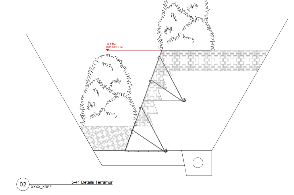
Section of the TerraMur system
Scaling the structure of a retaining wall in the right way is essential!